Bevel gear calculation (ISO 10300)
A bevel gear pair transmits torque between intersecting shafts, most often at 90°. ISO 10300 rates it through a pair of virtual cylindrical gears at the mean cone: part 1 gives that geometry and the load factors, part 2 the pitting resistance of the flanks.
Axomek computes the mean cone geometry, the forces on both shafts, the virtual cylindrical gears and the load factors of ISO 10300-1, and the pitting safety by ISO 10300-2 method B1. ISO 10300-3 is not implemented: the tooth root is rated on the virtual cylindrical pair by ISO 6336-3, with the load factors of ISO 10300-1.
- ISO 10300-1:2014
- ISO 10300-2:2014
- ISO 6336-3:2019
What Axomek calculates
You enter
- Tooth numbers, outer module met, face width, mean spiral angle βm, shaft angle Σ and pressure angle
- Pinion profile shift xhm1 (the wheel takes −xhm1) and the tooth form: straight (skew), spiral or Zerol
- Cutter radius and blade groups for spiral teeth (for KF0)
- Pinion torque in N·m, speed in rpm, application factor KA and life in h
- Mounting (straddle-mounted or overhung) and how the contact pattern is checked, the loaded pattern width, the ISO 17485 accuracy grade and the dynamic factor method
- σHlim and σFlim of pinion and wheel, the softer flank hardness for ZW, and the minimum safeties
It calculates
- Cone angles, outer cone distance, mean normal module and mean diameters
- Tangential, axial and radial forces on pinion and wheel at the mean diameter
- Virtual cylindrical gears: tooth numbers and the transverse, overlap and total contact ratios
- Load factors Kv, KHβ (with KHβ-be), KFβ (with KF0) and KHα = KFα
- Contact stress σH against σHP and the pitting safety SH of pinion and wheel
- Tooth root safety SF of pinion and wheel
Method and standards
- ISO 10300-1:2014 method B1 geometry with the virtual cylindrical gears of Annex A
- KA as an input (Annex C guide values); Kv by method B (resonance model) or method C (empirical curves), clause 7.7
- KHβ = 1.5·KHβ-be by method C from the mounting and the contact check (Table 4), KFβ = KHβ/KF0
- KHα = KFα by method B with the pitch deviation of the ISO 17485 grade
- Pitting by ISO 10300-2:2014 method B1 with ZM-B, ZLS, ZE, ZK and the factors ZL, Zv, ZR, ZW and ZNT
- Tooth root on the virtual cylindrical pair by ISO 6336-3 with the ISO 10300-1 load factors
Limits
- ISO 10300-3 (tooth root) is not implemented: its tooth form, load sharing and bevel spiral angle factors are not applied.
- Hypoid offsets are refused, as the hypoid geometry of ISO 23509 is not implemented; ZHyp is 1.
- The profile shift must satisfy xhm1 + xhm2 = 0, the case ISO 10300 covers.
- No scuffing check, no bevel slip factor (ISO 10300-2, informative Annex A) and no mounting on the project’s shafts.
Worked example
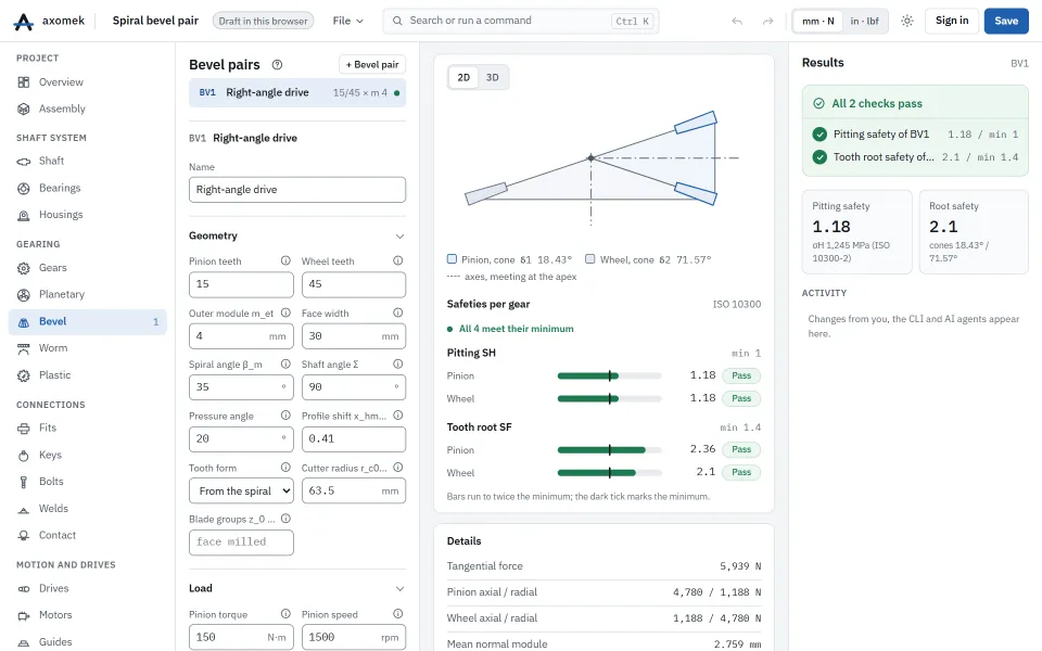
The spiral bevel pair template: 15/45 teeth, met 4 mm, Σ 90°, βm 35°, b 30 mm, xhm1 0.41, face milled with a 63.5 mm cutter radius, 150 N·m at 1500 rpm, KA 1.25, case-hardened 16MnCr5.
| Result | Value |
|---|---|
| Pinion cone angle δ1 | 18.43° |
| Tangential force Ft at the mean diameter | 5,939 N |
| Face load factor KHβ | 1.650 |
| Contact stress σH | 1,245 MPa |
| Permissible contact stress σHP | 1,466 MPa |
| Pitting safety SH (min 1.0) | 1.178 |
| Tooth root safety SF, pinion (min 1.4) | 2.355 |
| Tooth root safety SF, wheel | 2.105 |
Pinion and wheel share one contact stress, the same material and a life factor ZNT of 1, so their pitting safeties are equal; pitting is the closer check.
The numbers come from the engine: the same commands, run with the axm command line, give them.
The same with the axm command line
axm new ex.axm.json --template bevel-pair
axm solve ex.axm.json --jsonQuestions
How is the tooth root of a bevel gear rated without ISO 10300-3?
On the virtual cylindrical gear pair of ISO 10300-1 by ISO 6336-3, with the bevel load factors of ISO 10300-1 in place of those of ISO 6336-1. Part 3’s own factors are not applied.