Gear pairs
Rate external and internal spur and helical gear pairs by ISO 6336: geometry, load factors, pitting and tooth root safety, scuffing, load spectra, flank modifications and loaded tooth contact, and the mesh forces on a gearbox's shafts.
- ISO 6336-1:2006
- ISO 6336-2:2019
- ISO 6336-3:2019
- ISO 6336-5:2016
- ISO 6336-6
- ISO/TS 6336-20:2022
- ISO/TR 13989-2:2000
- ISO/TR 14179-1
The Gears module rates cylindrical gear pairs generated by a basic rack: spur or helical, external or internal (a ring gear). It gives the involute geometry with profile shift, the load factors, the pitting and tooth root safety of pinion and wheel, and optionally scuffing, a load spectrum and a loaded tooth contact analysis with flank modifications. Mounted on two shafts, a pair loads both shafts and their bearings with its tooth forces.
Inputs
Choose + Pair above the list of gear pairs (or Add a gear pair in an empty project). The inspector shows the groups below, from top to bottom. The pinion is always gear 1: torque, speed and the shaft layout refer to it.
Geometry
| Label | Unit | Notes |
|---|---|---|
| Pinion teeth z1, Wheel teeth z2 | The ratio . | |
| Normal module mn | mm | |
| Face width b | mm | Common face width. |
| Pressure angle αn | ° | 20 is the default. |
| Helix angle β | ° | 0 for spur gears; positive is a right-hand pinion. |
| Profile shift x1, Profile shift x2 | Without a given centre distance the pair runs without backlash at these shifts. | |
| Internal wheel (a ring gear) | Then Shaper cutter teeth sets the cutter that generates the ring's root (as many as the pinion when empty). |
Gear bodies
Pinion rim thickness and Wheel rim thickness (empty: solid) and the web widths. A rim thinner than 1.2 tooth depths (a ring's: 3.5 modules) raises the root stress by YB; a web narrower than the face lowers the mesh stiffness by CR.
Load
Pinion torque (N·m), Pinion speed (rpm), Application factor KA, Face load factor KHβ (used while no shaft layout is given), ISO 1328 grade (3–12, sets the pitch, profile and helix deviations) and Required life (h, typical 20 000 h) for the life factors ZNT and YNT.
Face load (method C)
Compute KHβ switches to ISO 6336-1 method C from the pinion shaft: Bearing span l, Pinion offset s from the span centre, Pinion shaft diameter and Arrangement constant K′ (0.48 for arrangement a with a stiff pinion shaft, ISO 6336-1 Figure 13). The shaft deflection fsh and the manufacturing misalignment fma combine, less the running-in, into Fβy. On the starter pair a 120 mm span and a Ø50 mm shaft give KHβ 1.462 instead of 1.2 (fsh 1.25 µm, fma 12.4 µm) and the pinion's SH falls from 1.377 to 1.247: the grade 6 helix deviations dominate, so a finer grade or a helix correction helps more than a stiffer shaft. Use a fixed KHβ instead goes back.
Gearbox mounting
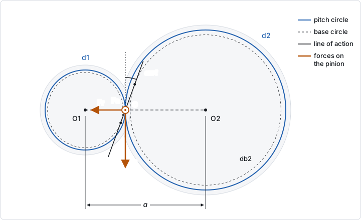
With two or more shafts in the project (add one in the shaft module), Mount on shafts places the pair: Pinion shaft, Wheel shaft, the mid-face positions and gear masses, Wheel direction (the mesh angle: from the pinion's axis to the wheel's, about +x from +y towards +z; the assembly view stands the shafts this way), Driving gear (Pinion (reduction) or Wheel (step-up)) and Pinion turns. The tooth forces then load both shafts at the working pitch circle (, radial , axial ) and the wheel shaft gets T·u·η, η the mesh efficiency. Let the input and output loads balance their shafts so they stay in equilibrium when η changes. In the Single-stage gearbox template the helical 20/60 × m3 pair (β 12°) puts its 1040 N axial force on bearings B1 and B4.
Accuracy and finish
Tip relief Ca (µm, in the dynamic factor Kv), Fillet roughness Rz, Rack dedendum hfP/mn (1.25), Rack root radius ρfP/mn (0.38), Pinion tip diameter da1 and Wheel tip diameter da2 (empty: standard), Life factor at 10¹⁰ cycles (1 = no decline beyond the knee, 0.85 where some decline must be assumed) and ISO 6336-2/-3 edition: 2019 (default) or 2006 (as ISO/TR 6336-30). The 2019 edition adds the load distribution factor fε to YF, divides Yβ by , gives helical gears the contact factor , takes ZV at the working pitch circle and widens ZW. ISO 6336-1 is applied in its 2006 edition either way.
Flank modifications
Choose Pinion or Wheel, then tip and root relief (amount, roll length or start diameter, Relief shape linear or parabolic), Profile crowning Cα, Lead crowning Cβ, Helix slope fHβ and End relief, all in µm normal to the flank. Mesh misalignment fβ (also ISO method C) adds a misalignment, for example a carrier's or a measured one; it enters both the loaded contact and the ISO face load factor. The modifications drive the loaded tooth contact and the scuffing load sharing; the ISO rating keeps Tip relief Ca.
Materials and lubrication
Pinion material and Wheel material come from ISO 6336-5:2016 quality MQ values:
| Material | σHlim (MPa) | σFlim (MPa) |
|---|---|---|
| Case-hardened 18CrNiMo7-6 | 1500 | 500 |
| Case-hardened 16MnCr5 | 1500 | 450 |
| Nitrided 31CrMoV9 | 1250 | 420 |
| Induction-hardened 42CrMo4 | 1150 | 360 |
| Through-hardened 42CrMo4 | 750 | 310 |
| Through-hardened C45 | 555 | 215 |
Oil viscosity at 40 °C (220 mm²/s) and Flank roughness Rz (3 µm) set ZL, ZV and ZR.
Scuffing
Check scuffing adds the check with Oil temperature 70 °C and FZG failure load stage 10. Further inputs: Oil base, Lubrication (Dip, Spray, Immersed), Structure factor XW, Flank roughness Ra (Rz/6 when empty), Oil viscosity ηoil (from ν40 when empty), Multiple path factor Kmp, Degree of run-in ΦE, Load sharing (From the tip reliefs by default), Oil with anti-scuff additives and The wheel drives (speed increaser). See gear scuffing.
Load spectrum
+ Bin adds a row of torque, speed (the pair's when empty) and share of the life. Each bin is rated with KA = 1, because the spectrum itself is the load variation.
Requirements
Min pitting safety SH (1.0), Min root safety SF (1.4), Min scuffing safety SintS (1.8) and Min scuffing safety SB (2.0; the TS sets none). Clear a field to disable that check.
Results
The right panel shows the verdict, Safety factors as bars per gear (they run to twice the minimum, the dark tick is the minimum), the contact and root stresses against their permissible values, Mesh efficiency by ISO/TR 14179-1 and Forces on the shafts (Ft at the reference circle, Fr, Fa, ratio u). The starter pair (20/60 × m3, b 30 mm, 150 N·m at 1500 rpm, KA 1.25, KHβ 1.2) gives:
| Result | Pinion | Wheel |
|---|---|---|
| Contact stress σH | 1082 MPa | 1004 MPa |
| Permissible σHP | 1490 MPa | 1490 MPa |
| Pitting safety SH | 1.377 | 1.484 |
| Root stress σF | 236.3 MPa | 223.6 MPa |
| Tooth root safety SF | 4.2 | 4.467 |
Ft is 5000 N and Fr 1820 N; the mesh loses 165.9 W of 23.56 kW (efficiency 99.3 %). Notes under the forces say where a simplified method reaches its limits; the gearbox template's pair, for example, notes that KHβ is the default 1.15 and that a shaft layout would compute it.
The views above the drawing:
- Mesh: the drawn mesh, the geometry and Rating factors (KHβ, c′ and cγα, resonance ratio N, Kv, KHα, KFβ, the Z factors, YF·YS, YB and CR).
- Tooth contact: the loaded tooth contact at the nominal torque (no load factors) with a Contact pressure or Separation map, the transmission error, mesh stiffness and line load across the face. On the starter pair a 13 µm long tip relief on both gears (about the single pair deflection ) cuts the transmission error from 6.06 to 0.68 µm peak to peak. With 10 µm misalignment KHβ is 1.548; 8 µm lead crowning on the pinion lowers it to 1.379, a 10 µm helix slope on the pinion to 1.000.
- Sliding and life: specific sliding along the path A–E, the permissible pinion torque and the safeties over lives of 10 h to 10⁶ h, and the load spectrum table with the damage sums.
- Scuffing (with a scuffing check): SB, θB max against θS and its margin, the flash temperatures, SintS and the temperatures along the path. With the starter defaults: SB 3.995 (θB max 121.0 °C against θS 273.6 °C, margin 152.6 K) and SintS 2.952.
- Root FE: the tooth root by plane finite elements beside ISO's YF·YS. For the starter pinion 2.925 against 2.830 (+3.4 %), the wheel 2.690 against 2.677.
Export STEP writes the pinion or the wheel (a ring gear cut by its shaper cutter) as a solid, with an optional bore.
A spectrum example
Bins of 250, 150 and 80 N·m with shares 0.1, 0.6 and 0.3 give spectrum safeties SH 1.196/1.289 and SF 3.17/3.371. The damage sums are 0 because every bin stays below the endurance limit, yet the safety is lower than the nominal one: the 250 N·m bin at KA = 1 exceeds the nominal 150 N·m × 1.25.
When a pair is refused
Each gear's contact must stay on its involute: the start of active profile, where the mate's tip meets the flank, has to lie at or above the form circle. Otherwise the solve stops with Can't solve this pair and says which tip meets which flank. For the starter changed to 14/60 teeth without shift:
involute interference: the wheel's tip meets the pinion 0.721 mm (roll length) inside its base circle Ø39.47 mm, where it has no involute; use a wheel tip diameter of at most Ø184.81 mm (details.tipDiameters), a positive pinion shift or more pinion teethTo fix it, give the pinion a positive Profile shift x1 (x1 = 0.3 lets this pair solve, though its pinion SH of 0.9991 then calls for more face width), add pinion teeth, or shorten the mate's tip with Wheel tip diameter da2. "Below its involute" means the tip reaches the root fillet above the base circle; the same levers apply. An internal ring without given tip diameters has its tip shortened only as far as needed to clear the pinion (Ø174.78 mm for the starter as a ring).
Fixing a failing check
- Pitting (SH): wider face, larger centre distance (module or teeth), a harder material, a finer grade or less misalignment (lower KHβ), a higher oil viscosity or a finer flank finish.
- Tooth root (SF): larger module, positive shift on the weaker gear, larger rack root radius, a thicker rim.
- Scuffing (SB, SintS): a higher FZG stage or anti-scuff oil, lower oil temperature, tip relief, lower sliding (shift balance), a finer flank finish.
Standards and scope
ISO 6336-1:2006 (Kv by method B, KHβ by method C or given, KHα by method B), ISO 6336-2 and -3 in the 2019 or 2006 edition, materials of ISO 6336-5:2016, load spectra by ISO 6336-6 (Palmgren–Miner), scuffing by ISO/TS 6336-20:2022 (flash temperature, Annex A) and ISO/TR 13989-2:2000 (integral temperature), mesh loss by ISO/TR 14179-1. The rating is checked against the worked examples of ISO/TR 6336-30 (axm verify).
Not covered: the size factor ZX (taken as 1); no-load losses (churning, windage); tooth bending coupling between slices, edge effects and dynamics in the loaded tooth contact; housing deflection and the mesh misalignment from shaft deflection in a gearbox (enter it as Mesh misalignment fβ). An internal pair's Mesh view lists the geometry without a drawing.
From the command line
axm new drive.axm.json --template gear-pair
axm gear update drive.axm.json G1 --patch '{"scuffing":{"oilTemperature":70,"fzgStage":10}}'
axm solve drive.axm.json
axm gear curves drive.axm.json G1 --json