Bolted joints
Single-bolt joints after VDI 2230-1:2015, steps R0 to R13: preload and tightening torque, load factor, embedding, and safeties against yield, fatigue, surface pressure, slipping and shearing.
- VDI 2230-1:2015
- ISO 898-1:2013
What it is for
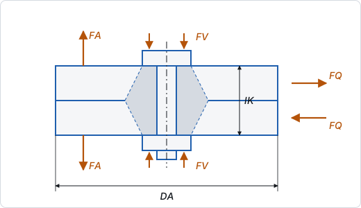
The Bolts module sizes a highly stressed bolted joint after VDI 2230-1:2015. It takes one bolt with its clamped parts and the loads that bolt carries, and works through the calculation steps R0 to R13 of the guideline (Section 4): the preload needed, the permissible assembly preload and the tightening torque, and the checks for the bolt, the clamped parts and the interface. Each joint is a single-bolt case: for a bolt pattern, work out the largest load per bolt first and enter that.
Inputs
Open Bolts and choose + Joint (or Add a joint). The inspector groups follow the order below. Loads are per bolt.
Bolt
- Thread: metric coarse threads M4–M36, shown with their pitch. Fine threads such as M12x1.25 can be set through the CLI.
- Property class: after ISO 898-1, 4.6 to 12.9. The yield strength and the minimum tensile strength Rm,min come from ISO 898-1 Table 3.
- Joint: Through bolt with nut or Screwed into a tapped thread.
- Head: Hexagon head (lSK 0.5·d) or Socket head cap screw (lSK 0.4·d), which sets the head's share of the bolt resilience.
- Thread friction μG and Head friction μK: minimum values. 0.10–0.14 is typical for lightly oiled steel threads; the template uses 0.12.
- Tightening method: Torque-controlled (elastic, ν·Rp0.2), Angle-controlled, beyond the yield point or Yield-controlled, beyond the yield point.
- For torque control, Tool and Tightening factor αA: Torque wrench 1.6, Precision torque wrench 1.4, Impact wrench 2.5, or your own value.
- For angle or yield control, αA is 1, and you give Largest thread friction μG,max (default μG) and Hardening kV (default 1.15; 1.1–1.2 is usual).
Bolt geometry
Head bearing dW and Hole dh default to the thread table (medium clearance holes, ISO 273); Bearing inner (chamfer) defaults to dh. Add a shank section describes a shank or reduced shank from under the head; without sections the bolt is threaded over the whole clamp length.
Clamped parts
- One row per plate from head to nut (for a tapped joint, without the tapped part): Thickness and Material. The materials set the modulus, the limiting surface pressure pG and the expansion: Steel S235 (pG 490 MPa), Steel S355 (760), Steel C45 (770), Steel 42CrMo4 (1300), Grey iron GJL-250 (850), Ductile iron GJS-400 (600), Aluminium AlMgSi1 F31 (360).
- Interface diameter DA (mm): the outer diameter of the clamped parts at the interface. Required.
- Roughness Rz (µm, default 6.3): sets the embedding after VDI 2230 Table 5.
Loads per bolt
- Axial working load FA,max and Least axial load FA,min (N): the range sets the alternating stress.
- Transverse load (N) and Plate friction μT (default 0.15): carried by friction in the interface.
- Torque about the axis MY (N·mm) with Friction radius ra (mm), for a joint that must also hold a torque by friction.
- Least clamp load (N): a residual clamp load the joint needs, for example for sealing.
Load introduction
Load introduction factor n: Enter n directly (0.5 when unknown, 1 when the load acts at the head and nut faces), or take it from Table 2, joint type SV 1 to SV 6 with Distance ak, Lever lA and Height h.
Eccentricity
Tick Eccentric clamping and loading, working moment for a joint whose bolt or load is off the axis of the deformation body. Then give Bolt offset ssym, Load offset a, Edge at risk u, Interface width cT and Body width b (signs after VDI 2230 Table 4), and optionally Working moment MB,max and Working moment MB,min.
Fatigue and thread engagement
Thread rolled after heat treatment (σASG) raises the fatigue limit. Load cycles NZ (finite life) applies below 2·10⁶ cycles. Check the length of thread engagement (R11) needs Engaged length and Nut / tapped part Rm, optionally Its shear strength τB and Outer diameter s. Bolt Rm (engagement, shearing) defaults to Rm,min of the class.
Temperature and requirements
Bolt ΔTS and Clamped parts ΔTP (K) are temperature rises over assembly; a bolt that grows more than the plates loses preload. Requirements sets the minimum safeties: yield 1, fatigue 1.2, pressure 1, slip 1.2, shear 1.1 by default.
Results
The right pane shows the checks and three key figures: Tightening torque MA (with FMzul), Preload needed (FMmin, with FMmax at αA) and the Load factor Φn (Φen* when eccentric). The centre shows Section through the joint with the deformation cone, the Joint diagram (force against deformation for bolt and plates) and Details.
In 3D the bolt (head, shank, thread), the nut or the tapped part and the clamped plates at their thicknesses and DA are cut away over a quarter, with the deformation cone see-through and the working loads as amber arrows; hovering plays a preload pulse. The 2D and 3D tabs above the drawing switch to a 3D model; the choice is kept for the module. In 3D, drag to orbit and scroll to zoom; the model stands still and plays its motion once when the pointer moves onto it or it gets the keyboard focus (never with reduced motion). Without WebGL the drawing stays, with a note.
The Bolted bracket template is an M12 8.8 through bolt with a hexagon head on two 15 mm S355 plates, DA 40 mm, μG = μK = 0.12, torque wrench αA 1.6, FA 6000 N and a transverse load of 2000 N per bolt:
| Result | Value |
|---|---|
| Stress area As, Rp0.2 / Rm | 84.27 mm², 640 / 800 MPa |
| Resilience bolt / plates | 2.769 / 0.616 µm/kN |
| Load factor Φn (n = 0.5) | 0.091, the bolt takes 546 N of FA |
| Embedding fZ | 9.5 µm, a preload loss of 2.806 kN |
| Required clamp load FKerf | 13.33 kN (2000 N / 0.15) |
| FMmin / FMmax | 21.59 kN / 34.55 kN |
| Permissible preload FMzul | 43.11 kN |
| Tightening torque MA | 83.59 N·m |
| Residual clamp load | 18.68 kN |
| Working stress σred | 547.3 MPa: yield safety 1.169 |
| Stress amplitude / σASV | 3.24 / 48.88 MPa: fatigue safety 15.09 |
| Surface pressure | 588.2 MPa against 760 MPa: safety 1.292 |
| Slip safety | 1.401 |
| Shearing τQ / τB | 23.73 / 520 MPa: safety 21.91 |
What each step does
- R1–R2: αA from the tool; the clamp load needed, , where FKQ holds the transverse load and MY by friction.
- R3: the load factor from the bolt and plate resiliences (deformation cone and sleeve), for a concentric through bolt; the bolt takes Φn·FA.
- R4: the preload lost to embedding (Table 5) and, with temperatures, the thermal change ΔF′Vth.
- R5–R6: , and .
- R7: FMzul, the preload at which the equivalent stress at assembly reaches ν·Rp0.2 (thread torsion included). The check passes when .
- R8: the working stress with the additional bolt load, torsion taken at kτ = 0.5, against Rp0.2.
- R9: the stress amplitude against the fatigue limit, for threads rolled before heat treatment.
- R10: surface pressure under head and nut against pG.
- R11: the least length of engagement, when ticked.
- R12: slip safety, the residual clamp load over FKQ, and shearing of the bolt against τB from Table 7.
- R13: the tightening torque MA for FMzul at μG and μK.
Fixing a failing check
- Preload above FMzul: a better tightening method (lower αA), a larger thread or a higher property class. Reducing FKerf (more interfaces, higher μT) also lowers FMmax.
- Yield safety: in the template it is 1.169, as close to its limit as the slip safety (both 86 % used). A larger thread or higher class helps; so does a lower thread friction, because torsion takes part of the yield strength.
- Fatigue: a longer, slimmer bolt (reduced shank) lowers Φ; rolling the thread after heat treatment raises the limit; avoid eccentric load paths.
- Surface pressure: a washer or a larger head bearing dW, or a plate material with a higher limiting pressure pG.
- Slip: more preload (lower αA, larger bolt), higher plate friction μT, or a form-fit element such as a dowel.
Standards and scope
- VDI 2230-1:2015, single-bolt joints, steps R0–R13, with the resiliences of Section 5.1, the load introduction of Table 2, eccentric clamping and loading (Section 5.3), partial opening after Annex D, the embedding of Table 5 and tightening beyond the elastic limit. Property class strengths after ISO 898-1:2013 Table 3.
- Verified in
axm verifyagainst the five calculation examples of Annex B (B1 piston rod, B2 flange coupling, B3 hollow flywheel bolt, B4 connecting rod cap, B5 cylinder cover; 103 checks), tabulated preloads and torques (14 checks) and ISO 898-1 stress areas and loads (20 checks). - R0, choosing the nominal diameter, is yours: the app checks the thread you give and warns when the eccentric model leaves its range.
- Not covered: the load distribution within a multi-bolt joint (VDI 2230-2), threads outside M4–M36 and non-metric threads, stainless (ISO 3506) and non-ferrous bolts, whose strengths are not in the property class list, and the preload-dependent thermal term of Eq. 117 (noted but not applied).
From the command line
axm new bracket.axm.json --template bolted-bracket
axm solve bracket.axm.json
axm bolt add flange.axm.json --name "Flange" --patch '{"thread":"M16","propertyClass":"10.9","axialLoad":25000,"transverseLoad":4000}' --json
axm guide bolts lists every field, including the eccentric and engagement objects.