Fits and press fits
ISO 286 limit deviations and clearances for a hole and shaft pair, and the elastic press fit of a hub on a shaft after DIN 7190-1: pressure, transmissible torque, stresses and shrink temperature.
- ISO 286-1
- ISO 286-2
- DIN 7190-1
What it is for
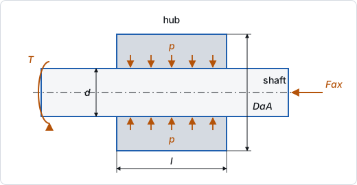
The Fits module answers two questions. First, which clearance or interference does a hole and shaft tolerance pair give at a nominal diameter (ISO 286)? Second, when you give the hub's outside diameter, can the joint carry its torque and axial force by friction, and do the hub and shaft stay elastic (DIN 7190-1)? Each fit is a stand-alone case: it is not attached to a shaft model. Bearing seat fits are handled in the Bearings module.
Inputs
Open Fits and choose + Fit (or Add a fit on the empty page). The inspector on the left shows these groups, top to bottom.
Fit
- Nominal diameter (mm): the joint diameter d.
- Hole and Shaft: the ISO 286 tolerance classes. The lists offer F7, G6, G7, H6, H7, JS6, JS7, K6, K7, M6, M7, N6, N7, P7, R7, S7 for the hole and f6, g5, g6, h5–h7, js5–js7, k5, k6, m5, m6, n5, n6, p6, p7, r6, s6 for the shaft. Through the CLI any of the letters F to S (f to s) with grades 4 to 7 is accepted.
With only this group filled in, the module is a limits-and-fits calculator: it shows the deviations, the clearance range and the fit type (clearance, transition or interference).
Press fit
- Hub outside diameter (mm): leave it empty ("no press fit") for a fit check only. A value turns on the DIN 7190 press fit analysis, for any tolerance pair. A pair with clearance has no contact pressure, so it transmits no torque by friction: its slip safety is 0 and fails, and the check's message says why.
- Joint length (mm): the length of the hub seat, default 40 mm.
- Hollow shaft bore (mm): 0 for a solid shaft. A bore lowers the pressure for a given interference and raises the shaft stress.
- Friction μ: the friction coefficient against slip. Typical values for a dry steel shrink fit are 0.12–0.15; the default is 0.12.
- Hub bore roughness Rz and Shaft roughness Rz (µm, default 4 each): part of the interference is lost when the peaks smooth out, 0.8·(RzA + RzI).
- Torque to carry (N·m) and Axial force to carry (N): the loads for the slip check.
- Speed (rpm, 0 or more; either way round alike): when the joint turns, the hub grows more than the shaft and loses interference.
- Assembly temperature (°C, default 20): the room temperature at assembly, also the base for the shrink temperature.
- Shaft operating temperature and Hub operating temperature (°C): a warmer shaft tightens the fit, a warmer hub loosens it.
- Hub modelled by a housing: shown only when the project has housings. A housing seat then replaces the thick-walled hub cylinder for the centrifugal growth when turning (its FE growth).
- Hub material and Shaft material: Steel S355, C45 +QT, 42CrMo4 +QT, Ductile iron GJS-400, Grey iron GJL-250 or Aluminium AlMgSi1. Each brings its modulus, Poisson's ratio, yield strength and expansion coefficient.
Requirements
- Min slip safety (default 1.5) and Min yield safety (default 1.1). Clear a field ("none") to switch that check off.
Results
The centre of the workspace shows Tolerance zones, a drawing of the hole and shaft zones about the nominal size. For a press fit it adds Stresses through the joint (radial and hoop stress from the shaft axis to the hub's outside at the largest interference) and a Press fit card. The right pane lists the checks and three key figures: Interference (max and min), Fit type and Transmissible torque (with the axial capacity and the pressure range).
In 3D the shaft and the hub are drawn at their diameters and the fit length, cut away over a quarter: the interference zone shows as a band coloured by the contact pressure over the pressure that yields the weaker part, and the cut faces by the hoop stress over each part's yield strength. Hovering presses the hub back on. The 2D and 3D tabs above the drawing switch to a 3D model; the choice is kept for the module. In 3D, drag to orbit and scroll to zoom; the model stands still and plays its motion once when the pointer moves onto it or it gets the keyboard focus (never with reduced motion). Without WebGL the drawing stays, with a note.
The Shrink-fit hub template (Ø50 H7/s6, C45 +QT hub of Ø100 × 50 mm on a 42CrMo4 +QT shaft, μ 0.12, 250 N·m) gives:
| Result | Value |
|---|---|
| Hole H7 / shaft s6 deviations | 0 … +25 µm / +43 … +59 µm |
| Interference | 18 … 59 µm |
| Lost to smoothing | 6.4 µm |
| Effective interference | 11.6 … 52.6 µm |
| Contact pressure p | 18.27 … 82.84 MPa |
| Transmissible torque | 430.5 N·m (or 17.22 kN axial) |
| von Mises hub / shaft | 191.3 MPa / 82.84 MPa (hub exact 193.3 MPa) |
| Shrink temperature | 218.2 °C |
| Comes loose at | 16 565 rpm |
| Slip safety | 1.722 (minimum 1.5) |
| Hub / shaft yield safety | 2.561 / 10.86 (minimum 1.1) |
The text output writes an interference as a negative clearance, so "clearance −59 … −18 µm" means 18 to 59 µm of interference.
What each result means
- Effective interference: the ISO 286 interference less the smoothing loss and, when temperatures differ, plus the thermal change . The capacity uses the smaller value of the assembly and operating state, the stresses the larger one. So a clearance pair that only the operating temperatures tighten (a hot shaft in a cooler hub) has its stresses checked at the operating interference, but carries nothing at room temperature, for example at a cold start: its slip safety is 0.
- Contact pressure from thick-walled cylinders in plane stress, with different materials for hub and shaft allowed.
- Transmissible torque and axial capacity at the smallest pressure: and . The slip safety compares F with the resultant of the circumferential force and the axial force, so torque and axial force share the same friction.
- von Mises hub / shaft at the largest pressure. The hub is checked with DIN 7190's value at the bore, ; the exact plane-stress value is shown next to it and is about 1 % higher at Q = 0.5.
- Shrink temperature: the hub temperature that opens the largest interference plus an assembly clearance of 0.001·d, with the shaft at the assembly temperature.
- Comes loose at: the speed at which centrifugal growth of the hub eats the smallest interference. With a Speed set, a Turning line shows the interference lost, the hub's hoop stress, the pressure left and the torque that can still be transmitted; the slip check then uses the turning state.
As an example of the operating state, the template with a shaft at 60 °C, a hub at 40 °C and 3000 rpm gives an interference change of +11 µm (tighter), a peak pressure of 100.2 MPa and a hub yield safety of 2.115. At speed 0.38 µm is lost, 416.4 N·m can be transmitted and the slip safety falls to 1.665.
Fixing a failing check
- Slip safety too low: choose a tighter shaft class (r6 → s6; a clearance or transition class such as g6 or k6 has no grip at its loosest), make the joint longer or larger in diameter, use smoother seats (less smoothing loss), or check whether a higher friction coefficient is justified for your surfaces. A larger hub outside diameter also raises the pressure for the same interference.
- Hub yield safety too low: increase the hub outside diameter, use a stronger hub material, or choose a looser class. The largest interference sets the stress, so a finer tolerance grade, which narrows the interference range, helps as well.
- Shaft yield safety too low: usually only with a hollow shaft. Reduce the bore or use a stronger shaft material.
- Shrink temperature too high for the hub's heat treatment: choose a looser class, or plan to cool the shaft; the app reports only the hub heating temperature.
Standards and scope
- Limit deviations after ISO 286-1 and ISO 286-2. The deviations are verified against the ISO 286-2 tables in
axm verify("Limits and fits: ISO 286 and ISO 492", 26 checks). - Press fit after DIN 7190-1, elastic range only: plane stress, thick-walled cylinders, solid or hollow shaft, different materials. The DIN 7190-1 text itself was not available for this help page; the method summary comes from the app's method notes.
- Rotating hub after the rotating thick-walled cylinder, or from a linked housing seat's FE growth.
- Not covered: elastic-plastic press fits, stepped or non-cylindrical hubs (except through a linked housing), conical press fits, fretting and fatigue of the joint, and the stress concentration at the hub edge. The press fit as a notch in the shaft is part of the shaft strength check.
From the command line
axm new hub.axm.json --template shrink-fit
axm solve hub.axm.json
axm fit add hub.axm.json --name "Coupling hub" --patch '{"diameter":60,"holeClass":"H7","shaftClass":"r6","hubDiameter":110,"length":60,"torque":900}' --json
axm guide fits lists every field with its unit and default.
Related
- ISO 286 and DIN 7190 press fits
- Tutorial: shrink-fit hub
- Open the Shrink-fit hub example
- Keys and splines
- Bearings for bearing seat fits
- Housings for a turning hub modelled by finite elements
- Shaft strength