Weld groups
Fillet, full- and partial-penetration butt weld groups in one face plane after EN 1993-1-8, with throat stresses by the directional or simplified method and fatigue over a load spectrum after EN 1993-1-9.
- EN 1993-1-8:2005
- EN 1993-1-9:2005
What it is for
The Welds module checks a group of straight weld lines that join a part to a face, for example a bracket on a column flange or a lug on a plate. You draw the lines in the face plane, give the forces and where they act, and the module finds the throat stresses along every line, the utilisation by the directional or simplified method of EN 1993-1-8 and, with a load spectrum, the fatigue damage after EN 1993-1-9. The lines are coloured by their utilisation, so the critical end of a weld is easy to see.
Inputs
Open Welds and add a weld group: Bracket (C of fillet welds) or Box (four fillet welds) as a starting shape. The inspector groups are:
Weld lines
Start, end and throat a: one row per line with x₁, y₁, x₂, y₂ (mm, in the face plane) and the throat a (mm). For a fillet weld a is the throat thickness, not the leg length; for an equal-leg fillet the throat is about 0.7 times the leg. For a full-penetration butt weld give the thinner plate; for a partial-penetration butt weld give the depth of penetration.
The kind of each line is chosen in the table under the drawing, column Type: Fillet, Butt (full penetration) or Butt (partial penetration). For a partial-penetration weld, depth proven (else − 2 mm) counts the full depth when procedure tests prove it; otherwise the effective throat is 2 mm less (EN 1993-1-8, 4.7.2).
Steel and method
- Steel: S235, S275, S355, S420 or S460. Each sets fu, fy and βw (for S355: fu 510 MPa, fy 355 MPa, βw 0.9), from EN 1993-1-1 Table 3.1 for t ≤ 40 mm.
- Ultimate strength fᵤ, Yield strength fᵧ (butt welds) and Correlation factor βw: leave empty ("of the grade") unless the weaker part differs.
- γM2 (default 1.25) for the welds and γM0 (default 1) for butt welds as the parent metal.
- Method: Directional (4.5.3.2) or Simplified (4.5.3.3).
Loads
Design values (already factored). Force Fx (in the face), Force Fy (in the face) and Force Fz (out of the face) in N act at the point Forces act at x, y, z (mm; z points out of the face towards the load). Moment Mx, My, Mz (N·mm) are added to the moments the forces make about the centroid.
Fatigue (EN 1993-1-9)
Closed by default. Ranges (× the loads) and cycles: blocks of stress ranges, each a multiple of the stresses from the loads above, with its number of cycles. With at least one block you also get Detail category Δσc (default 36 MPa, root failure of load-carrying fillet welds) and Detail category Δτc (default 80 MPa), and the partial factors γFf (default 1) and γMf (default 1.35). A line can have its own categories in the table (Δσc / Δτc column), for example a full-penetration butt weld from EN 1993-1-9 Table 8.3.
Requirements
Max utilisation (default 1) and, with fatigue, Max damage sum (default 1).
Results
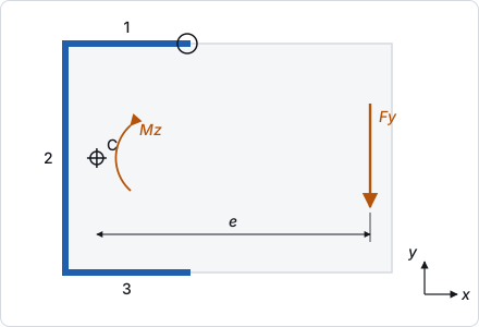
The drawing shows the lines coloured from 0 to 100 % utilisation, the centroid, the in-plane load and the most loaded point. The key figures are Utilisation (with both methods), Equivalent stress (with σ⊥, τ⊥ and τ∥ at the critical point) and Fatigue damage. The facts list the throat area and polar moment, the centroid, the loads at the centroid, the design strengths and the fatigue ranges.
In 3D the base plate lies in the face plane, the attached member stands on the weld lines and the beads (fillets at their throats a) are coloured along their length by the utilisation, the load an amber arrow at its point; hovering pulses the load. The 2D and 3D tabs above the drawing switch to a 3D model; the choice is kept for the module. In 3D, drag to orbit and scroll to zoom; the model stands still and plays its motion once when the pointer moves onto it or it gets the keyboard focus (never with reduced motion). Without WebGL the drawing stays, with a note.
The Welded bracket template has two groups in S355. WD1 is a bracket on a column flange held by a C of 5 mm fillet welds (two 80 mm flanges and a 150 mm web line) under Fy = −40 kN at x = 200 mm, y = 75 mm, with a two-block fatigue spectrum (0.3 × the load for 100 000 cycles, 0.15 × for 2 000 000 cycles). WD2 is a lifting lug on two 120 mm lines with a = 6 mm, pulled by Fz = 30 kN and Fx = 8 kN at z = 80 mm.
| Result | WD1 bracket | WD2 lifting lug |
|---|---|---|
| Throat area | 1550 mm² | 1440 mm² |
| Centroid | (20.65, 75) mm | (0, 0) mm |
| Polar moment Ip | 6 952 272 mm⁴ | 1 764 000 mm⁴ |
| Moment at the centroid | Mz −7 174 194 N·mm | My 640 000 N·mm |
| Most loaded point | line 1 at (80, 150) | line 1 at (−60, 5) |
| σ⊥ / τ⊥ / τ∥ | −61.56 / 61.56 / 77.39 MPa | 30.44 / 30.44 / 5.556 MPa |
| Equivalent stress | 182 MPa | 61.65 MPa |
| Utilisation, directional / simplified | 40.15 % / 44.51 % | 13.6 % / 16.59 % |
| Fatigue damage | 0.09884 (normal stress, line 1) | no spectrum |
The design strengths for S355 are , and fvw,d = 261.7 MPa. WD1's spectrum could be applied 10.12 times before the damage sum reaches 1.
What each result means
- Section properties: each line is taken as a strip of its throat turned into the face plane. The group's area, centroid, Ix, Iy, Ixy and polar moment Ip come from these strips.
- Stresses: the forces are moved to the centroid. In the face plane the shear is F/A plus ; across it, plus bending about the principal axes. For each line the stress is split into τ∥ along the line and, for fillet welds, into σ⊥ and τ⊥ on the 45° throat, taking the worse of the two sides. Eleven points per line are evaluated.
- Directional method (4.5.3.2): and . The utilisation is the larger ratio. For WD1: 182/453.3 = 40.15 %.
- Simplified method (4.5.3.3): the resultant force per unit length against fvw,d·a. It is the more conservative of the two methods, as the 44.51 % against 40.15 % shows.
- Full-penetration butt welds: checked as the weaker parent plate, .
- Fatigue: on the throat, and , with S–N curves through the detail categories (slope 3 then 5 for normal stress, slope 5 for shear, cut-off at 10⁸ cycles), the partial factors and Palmgren–Miner summation at every point. The damage is the sum of the normal and shear parts.
Fixing a failing check
- Strength: a larger throat on the critical line, longer lines, or a group whose centroid lies closer to the load line (less torsion). Spreading the lines apart raises Ip and lowers the torsional shear.
- Fatigue: the throat helps through the stress range. Changing the detail (a full-penetration weld with a better category, ground welds) only helps when the line is given that category; the default 36 MPa assumes root failure of a load-carrying fillet weld.
- A higher steel grade helps the static check only through fu and βw, and does not change the fatigue categories.
Standards and scope
- EN 1993-1-8:2005 4.5.3.2 (directional method), 4.5.3.3 (simplified method) and 4.7.2 (partial-penetration butt welds); full-penetration butt welds as the parent metal.
- A fillet weld the standard does not let carry load is refused where it is, by either method: a throat below 3 mm (4.5.2(2)), or an effective length below 30 mm or 6 times the throat (4.5.1(2)). Fillet lines joined end to end count as one weld for its length, so a curved weld drawn as short straight lines, or a weld run round a corner, is judged by its whole length.
- EN 1993-1-9:2005 nominal stress method with the detail categories of Table 8.5 (detail 3, root failure 36*, and detail 8, shear 80, by default) or per line.
- Steel strengths of EN 1993-1-1 Table 3.1 for t ≤ 40 mm.
- Not covered: weld lines out of one plane, curved or circular welds (approximate them with short straight lines), the side on which the attached part stands (the worse 45° throat is taken), hot-spot and effective-notch fatigue methods, stainless and aluminium welds, and lamellar tearing. There is no weld-specific case in
axm verifyyet.
From the command line
axm new bracket.axm.json --template welded-bracket
axm solve bracket.axm.json
axm weld add frame.axm.json --name "Bracket" --patch '{"lines":[{"x1":0,"y1":150,"x2":80,"y2":150,"throat":5},{"x1":0,"y1":0,"x2":0,"y2":150,"throat":5},{"x1":0,"y1":0,"x2":80,"y2":0,"throat":5}],"grade":"s355","loads":{"fy":-40000,"x":200,"y":75}}' --json
axm guide welds lists every field with its unit and default.