Units and conventions
The units the app shows and stores, the shaft's axes, the signs of forces and moments, and how positions are measured.
Read this page before you enter real loads. Most surprises in a first model come from a sign or a unit.
Units
The app shows metric or US customary units. Switch with mm · N and in · lbf in the top bar, or in Settings › Display › Units.
| Quantity | Metric | US customary |
|---|---|---|
| Length, diameter | mm | in |
| Force | N | lbf |
| Moment, torque | N·mm or N·m | lbf·in or lbf·ft |
| Stress, pressure, modulus | MPa | ksi |
| Temperature | °C | °F |
| Power | W, kW | hp |
| Oil viscosity | mm²/s | mm²/s (cSt) in both |
| Speed | rpm | rpm |
| Tilt, slope | ′ (arc minutes) | ′ |
The switch changes the display only. The project file always holds metric base units: mm, N, N·mm, MPa, N/mm, N·mm/rad, arc minutes, kg/m³. A file therefore gives the same results on every computer, whatever its settings.
In any number field you can type a unit with the value. 2 in, 3 kN, 49.4 N·m and 30 ksi are converted to the field's unit. A bare number is read in the unit the field shows. See Units and number entry for the full list.
The shaft's axes
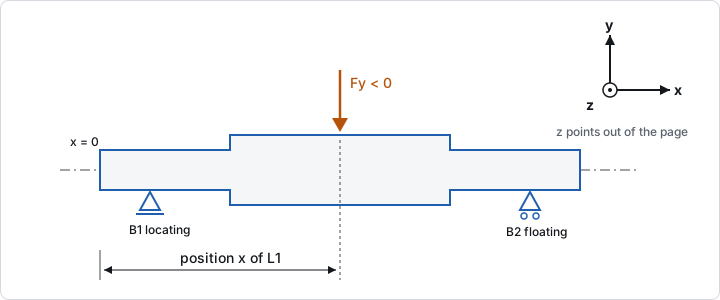
- x runs along the shaft's axis, from its left end (x = 0) to its right end.
- y and z are the two lateral directions. x, y and z form a right-handed set.
- The xy plane and the xz plane are the two bending planes. The drawing and the charts show one of them at a time; switch with xy plane and xz plane above the drawing.
Every position along a shaft is measured from its left end, in mm: section boundaries, supports, loads, notches, gear seats. A section's x is where it starts. Sections follow each other from left to right without gaps.
In a gearbox each shaft has its own x axis, starting at its own left end. All shafts are parallel and share the y and z directions.
Signs of forces and moments
| Input | Positive direction |
|---|---|
| Force y, Force z | Along +y, +z. A load pushing down in the xy plane is a negative Force y. |
| Axial force x | Along +x, from the left end towards the right end. |
| Moment xy | Turns +x towards +y. |
| Moment xz | Turns +x towards +z. |
| Torque | About the shaft's axis. |
The torques on one shaft must balance: power in equals power out. Give the input coupling +T and the output −T, or tick Takes the torque that balances the shaft on the output load. That load then takes whatever torque the other loads leave, also when a gear's efficiency or a speed changes. At most one load per shaft can do this.
A mounted gear pair puts its tooth forces on both shafts. Its direction is the angle from the pinion's axis to the wheel's, about +x, measured from +y towards +z. Belt and chain drives use the same angle.
A bearing analysed on its own, without a shaft, takes its loads as Fx (axial) and Fy, Fz (radial), in N, and moments My, Mz in N·mm. The moments follow the right-hand rule.
Supports
- A Locating support holds the shaft axially. Axial loads go to it.
- A Floating support lets the shaft move axially, for example as it grows with temperature.
- Normally one support is locating. Two locating supports make a cross-located shaft, such as an X or O pair of tapered roller bearings. Each of them then needs an axial stiffness.
- A support without a stiffness is rigid. A Radial stiffness (N/mm) or Tilt stiffness (N·mm/rad) makes it a spring.
Results and their signs
- Deflection is the shaft's lateral displacement in the plane shown, in mm (µm for small values).
- Bending moment is E·I times the curvature, per plane.
- Shear force is the sum of the lateral forces to the left of the cut.
- Tilt at a support is the shaft's slope there, in arc minutes. Bearings tolerate only a few minutes of tilt; see Shaft.
- von Mises stress combines bending, axial and torsional stress. It is the nominal stress: notches and shoulders are assessed separately by the strength check.
Ids
The app names items as it creates them: sections S1, S2, …; supports B1, B2, …; loads L1, L2, …; bearings BR1, BR2, …; further shafts SH2, SH3, …; gear pairs G1, …; bolted joints J1, …. Ids stay the same when you rename an item, so scripts and agents can rely on them. They are unique across all shafts of a project.
Unlimited and missing values
A life or safety that has no limit, such as the life of a bearing the shaft leaves unloaded, is shown as "unlimited". A value that was not computed is left empty.