Shaft strength (DIN 743 and FKM)
Fatigue and static safety of the shaft at shoulders, notches and its weakest plain sections, after DIN 743 or the FKM guideline.
- DIN 743-1:2012
- DIN 743-2:2012
- FKM guideline, 7th edition (2020)
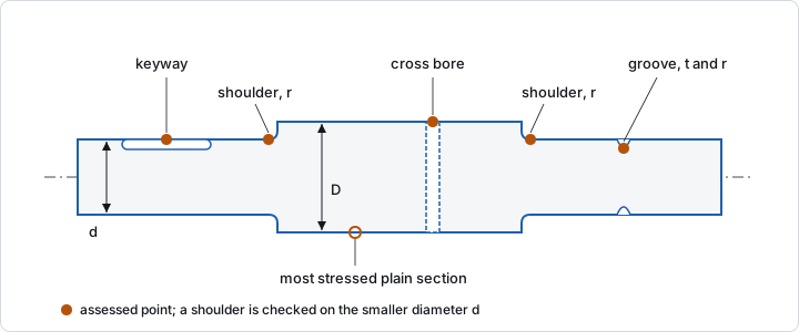
The strength check assesses the shaft against fatigue and yielding at the places where it is most likely to fail: every diameter step (a shoulder), every notch you add (keyways, grooves, press fits, cross bores and others) and the plain sections of lowest fatigue and lowest static safety. It uses the nominal stresses from the shaft solution and applies notch, size, surface and mean stress factors after DIN 743 or the FKM guideline. The result is a fatigue safety and a static safety at each point (DIN 743), or degrees of utilisation aBK and aSK (FKM).
Adding the check
Open the Material tab of the shaft inspector. The Strength (DIN 743) group starts empty; choose Add strength check. It starts with C45 +QT (σB 700 MPa, σS 490 MPa at Ø16 mm), Rz 6.3, a fillet radius of 1 mm at every step and minimum safeties of 1.2. Remove strength check at the bottom takes it off again.
Inputs
Method and material
| Field | Meaning |
|---|---|
| Method | DIN 743 (2012) or FKM guideline (nominal stresses). Both assess the same points with the same nominal stresses. |
| Steel | A preset: C45 +QT 700/490, 34CrMo4 +QT 1000/800, 42CrMo4 +QT 1100/900, 34CrNiMo6 +QT 1200/1000, 16MnCr5 core 1000/695, 18CrNiMo7-6 core 1200/850, E335 570/335 (σB/σS in MPa at Ø16 mm). |
| Tensile strength σB, Yield strength σS | MPa, at the reference diameter. Edit them for another steel. |
| Size effect (strengths given at Ø16 mm) | How the strengths fall with size (the technological size factor K1 of DIN 743-2, clause 6.2): Quenched and tempered, Case-hardening steel (core), Cr-Ni-Mo case-hardening steel (core), Structural steel, Nitriding steel, or Strengths valid for this size (K1 = 1). |
The strengths are reduced to the largest diameter of the shaft. The results note gives the values used, for example "C45 +QT: σB 618.3 MPa, σS 415.2 MPa at Ø45 mm".
Surface and loading
| Field | Unit | Meaning |
|---|---|---|
| Surface | µm | Roughness Rz: Rz 1.6 · polished, Rz 3.2 · ground, Rz 6.3 · fine turned, Rz 12.5 · turned, Rz 25 · rough turned. |
| Fillet radius at steps | mm | Radius of every diameter step that has no Shoulder radius notch of its own. |
| Torque amplitude | % | Alternating part of the torque. 0 is a steady torque. |
| Peak load factor | Multiplies all loads for the static check, for example a start-up torque. 1 by default. | |
| Min fatigue safety, Min static safety | DIN 743 only. 1.2 is the usual minimum when the loads are well known. | |
| Surface treatment | None, Nitrided, Case hardened, Carbonitrided, Induction or flame hardened, Deep rolled, Shot peened. Credits the surface factor KV. | |
| Layer strength σBRand | MPa | DIN 743 with a hard layer. Empty is 2300 MPa for case hardening and 1700 MPa for nitriding. Carbonitrided and induction hardened layers need a value, else the incipient crack check is skipped with a warning. |
| Mean stress | Grows with load (case 2) (the conservative default) or Constant (case 1); for FKM, F2 and F1. | |
| Rotating shaft (bending fully reversed) | On for a shaft that turns under fixed loads. Off when the bending stress is constant. |
Notches
Every diameter step is checked as a shoulder automatically. Choose + Notch for anything else, then set its Kind, Position and size:
| Kind | Size inputs | Notes |
|---|---|---|
| Keyway | End-milled keyway (DIN 6885 form A); notch factors of DIN 743-2 Table 1. | |
| Two keyways | 180° apart: the keyway's factors × 1.15. | |
| Groove | Radius, Depth | Round-bottomed groove, for example an undercut. |
| Retaining-ring groove | Root radius, Depth, Width | DIN 471 groove; measured factors of DIN 743-2, 4.2.4. |
| V-notch | Depth | Thread-like notch, root radius 0.1 mm; DIN 743-2, 4.2.3, for t/d 0.05 to 0.2. |
| Cross bore | Bore radius | Transverse bore; DIN 743-2, 5.2.3, for 2r/d up to 0.3; stresses on the net section. |
| Press fit | Edge of a hub or bearing ring pressed on; DIN 743-2 Table 1. | |
| Shoulder radius | Radius | Place it at a diameter step to override the fillet radius there. |
| Plain section | An extra point to check without a notch. |
A shoulder is assessed on the smaller of the two diameters, with that section's forces and bore. Every plain cross-section along the shaft is assessed, and the one with the lowest fatigue safety and the one with the lowest static safety are added: as "Plain section" when one place has both, else as "Plain section (fatigue)" and "Plain section (static)". They often differ: on a rotating shaft fully reversed bending lowers the fatigue safety far more than a steady torque does, which still raises the von Mises stress. A plain section that a notch or an explicit plain section already assesses (the same place, section and forces) is left to it; one merely close by is not, since a concentrated moment or force steps the forces between two places however close, so adding assessments never raises the lowest safety. A point between two nodes of the solver's mesh takes the forces there, the bending of the shaft's own weight between the nodes included, so the results do not depend on the mesh.
FKM settings
With FKM guideline (nominal stresses) the group becomes Strength (FKM) and adds:
| Field | Meaning |
|---|---|
| FKM material group | Quenched and tempered, case-hardening, structural, stainless or austenitic stainless steel, cast steel (GS), nodular cast iron (GJS), wrought or cast aluminium. Sets the fatigue strength factors, the roughness, support number and mean stress constants and the S-N curve. |
| Safety class | Consequences of failure and inspection, from High consequences, not inspected · jF 1.5 to Low consequences, inspected · jF 1.2. |
| Probability of the peak load (static) | High or Low (rare, well known): sets jm and jp. |
| Casting inspection | Cast groups only: jG 1.4, 1.25 or 1.0. |
| Size exponent ad,m, ad,p, deff,N,m, deff,N,p | Empty takes the grade's row in the FKM material tables (by name, e.g. C45, 42CrMo4, 16MnCr5, S355) or the group's default. |
| Load cycles | Empty is infinite life. A number makes it a finite-life check; with a duty cycle, damage is accumulated over the load cases, at each notch and at the plain section where the load cases together do the most damage (not necessarily where any one case is worst). |
| Anisotropy KA | 1 by default (loaded along the rolling direction). |
| Temperature | °C. Above the normal range (steel from 100 °C) the temperature factors lower the strengths. |
| Miner sum Dm | Empty uses eq. 2.4.41. |
| Damage accumulation (duty cycle) | Miner consistent (default) or Miner elementary. |
| Age-hardenable alloy | Aluminium only. |
FKM has no minimum safeties to type: the safety factors jD and jges are built in, and a point passes when aBK ≤ 1 and aSK ≤ 1.
Results
The results column gets a Strength (DIN 743) or Strength (FKM) section:
- Two tiles: Fatigue safety and Static safety (FKM: Fatigue utilisation aBK and Static utilisation aSK) at the governing point.
- One row per point with its value and a bar that fills towards the required safety, then its position, diameter, notch factor (βσ for DIN 743, Kf for FKM) and static result.
- A note with the material strengths at the effective diameter (FKM: Rm, Rp, jD and jges).
Two checks join the checks banner: Fatigue safety (DIN 743 / FKM) and Static safety (DIN 743 / FKM). With DIN 743 they compare the lowest safety with Min fatigue safety and Min static safety. With FKM they compare the safety jD/aBK with jD and jges/aSK with jges, so their utilisation is aBK and aSK. With a hard layer, the incipient crack safety is part of the static safety. Each notch in the inspector list also shows its safety.
Fixing a failing check
- Enlarge the diameter at the point; stress falls with its cube.
- Increase the fillet radius at the shoulder, or move a keyway away from the highest bending moment.
- Choose a stronger steel or a finer surface.
- Add a surface treatment (deep rolling, shot peening, nitriding or case hardening) for the KV credit.
- With FKM, check the safety class and whether Load cycles describes the real life.
Example: the gearbox intermediate shaft
The gearbox intermediate shaft template has no strength check. Add one with its defaults (C45 +QT, Rz 6.3, fillet radius 1 mm) and two keyways, at the gear (x = 80 mm) and at the pinion (x = 180 mm). It gives, with DIN 743 (σB 618.3 MPa, σS 415.2 MPa at Ø45 mm):
| Point | x mm | Ø mm | βσ | Fatigue safety | Static safety |
|---|---|---|---|---|---|
| Shoulder S1/S2 | 25 | 30 | 1.921 | 11.82 | 46.32 |
| Gear keyway | 80 | 38 | 2.495 | 3.268 | 12.57 |
| Shoulder S2/S3 | 120 | 38 | 1.998 | 3.127 | 11.53 |
| Shoulder S3/S4 | 130 | 38 | 1.998 | 2.982 | 11.13 |
| Pinion keyway | 180 | 38 | 2.495 | 2.03 | 8.685 |
| Shoulder S4/S5 | 235 | 30 | 1.921 | 7.137 | 27.98 |
The pinion keyway governs: fatigue safety 2.03 against 1.2 (59 %), static safety 8.685 against 1.2 (14 %). The shoulders at 120 mm and 130 mm are assessed on the Ø38 sections next to the Ø45 collar.
Switched to FKM with the default safety class (jD 1.5, jges 1.5; Rm 659.7 MPa, Rp 423 MPa at Ø45 mm), the pinion keyway governs again with aBK 0.6927 and aSK 0.1234, so the fatigue safety is 2.165 against jD 1.5.
Standards and scope
- DIN 743-1/-2:2012, nominal stresses from the shaft solution. Notch factors from DIN 743-2 (formulas for shoulders, grooves and cross bores; measured factors for keyways, press fits, retaining-ring grooves and V-notches), geometric size factor K2, roughness factor KF, surface factor KV from the lower bounds of Table 4, and mean stress cases 1 and 2. Compressive mean stresses follow Annex A of part 1. The static check uses the component yield point.
- FKM guideline, 7th edition (2020), nominal stress approach for non-welded rod-shaped parts: chapter 1 (static) and chapter 2 (fatigue), with the size factor from the FKM material tables, Kf from the stress gradients, KR, KV, the mean stress factor, the variable amplitude factor and damage accumulation over a duty cycle.
- The DIN 743 group of
axm verifyrecomputes the three worked examples of DIN 743 Beiblatt 1:2024-07. The FKM group reproduces the guideline's worked examples 6.1 and 6.2.
What is not covered:
- Material data. DIN 743-3 material tables are not built in beyond the seven preset steels. The material fatigue limits are taken as 0.5·σB in bending and 0.3·σB in torsion; 0.4·σB in tension is kept as before, since the available documents do not print it. Enter σB and σS from your material certificate for other steels.
- DIN 743 life. DIN 743 here is an endurance-limit check. With a duty cycle the worst load case governs; there is no damage accumulation. When the shaft cannot be solved for a load case (for example an axial load that no locating support takes), the fatigue and static safety checks are left out, since the worst case is not known, and the results are marked as not completely computed. Use FKM with Load cycles for finite life and spectra.
- Local stresses. Only the nominal stress approach. The local stress approach of FKM and its material-mechanics support number are not used. The shaft's own stress results (and the stress limit) contain no notch effects.
- FKM factors set to 1. Coating and residual stress factors are 1, and creep (KTt) is not considered. Cross bores take Kt from DIN 743-2 Bild 12, as FKM section 5.2 has none for round bars. Stainless steel gets no temperature factor above 100 °C.
- Surface treatment. KV is always the lower bound of the tables.
- Geometry limits. Cross bores up to 2r/d = 0.3, V-notches for t/d from 0.05 to 0.2.
From the command line
axm new shaft.axm.json --template gearbox-intermediate
axm apply shaft.axm.json '{"op":"updateStrength","patch":{"notches":[{"id":"N1","position":80,"kind":"keyway"},{"id":"N2","position":180,"kind":"keyway"}]}}'
axm solve shaft.axm.json
axm guide shaft-strength