Shaft strength: DIN 743 and FKM
How the fatigue and static safety of a shaft is assessed at shoulders, notches and plain sections after DIN 743:2012 or the FKM guideline (7th edition), and how the app applies both methods.
- DIN 743-1:2012
- DIN 743-2:2012
- DIN 743 Beiblatt 1:2024
- FKM guideline, 7th edition (2020)
The shaft solution gives nominal stresses on the plain cross-section. A shaft fails where a shoulder, groove, keyway or press fit raises the local stress, and usually by fatigue long before its static strength is reached. The strength check turns the nominal stresses at each critical section into a fatigue safety and a static safety, by one of two nominal-stress methods: DIN 743 (the default, DIN 743 (2012) in the strength panel) or the FKM guideline (FKM guideline (nominal stresses)).
The app assesses every diameter step as a shoulder, each notch you add (Keyway, Two keyways, Groove, Retaining-ring groove, V-notch, Cross bore, Press fit, Shoulder radius, Plain section) and the plain sections of lowest fatigue safety and of lowest static safety. These are found separately along the whole shaft, at every node and, under the shaft's weight, between nodes: the place of highest von Mises stress need not be either, since a steady torque raises the von Mises stress far more than it lowers the fatigue safety of a rotating shaft, whose bending is fully reversed. A shoulder is checked on its smaller diameter, with the forces and bore of that smaller section.
Nominal stresses
DIN 743-1, 4.2 and Table 1, defines the working stresses from the section forces: for tension or compression, for bending and for torsion, with and for a hollow section. Each stress has an amplitude (index a) and a mean value (index m).
In the app a rotating shaft (rotating on, the default) sees its bending moment as a fully reversed amplitude: a fibre passes the tension and the compression side once per revolution, so and σbm = 0. The torque is steady unless you give a Torque amplitude as a fraction of the nominal torque. The axial stress keeps its sign, so a compressive axial load gives a negative mean stress. For the static check all loads are multiplied by the Peak load factor (for example a start-up torque).
Stress concentration and notch factors
The stress concentration factor α (Formzahl) is the ratio of the peak elastic stress to the nominal stress, . It depends only on geometry. The fatigue notch factor β (Kerbwirkungszahl) is the ratio of the fatigue limit of the plain specimen to that of the notched one. It is smaller than α, because a steep stress gradient means that only a small volume is highly stressed and the material around it supports it.
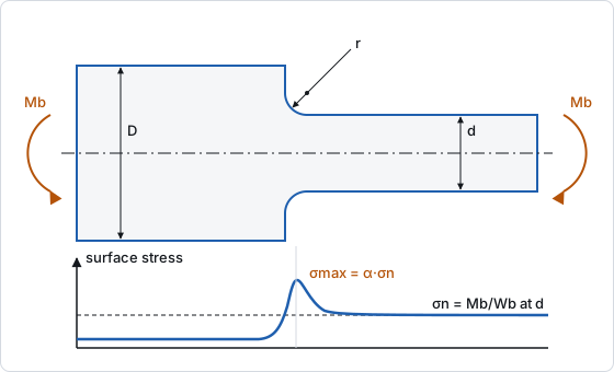
DIN 743-2 obtains β in two ways:
- From α and the support number (clause 4.3): , eq. (4), with α from eq. (9) and Table 3 for shoulders and round grooves, and n from the related stress gradient G′ by eq. (5), or eq. (6) for hard surface layers. The app applies this to shoulders, round grooves and cross bores (clause 5.2.3, stresses on the net section).
- Measured notch factors (clause 4.2): keyways and press fits (4.2.1, Table 1), V-notches (4.2.3) and retaining-ring grooves (4.2.4). They are given for a reference diameter and scaled to the actual diameter by K3 (eq. (3) with eq. (17)). Two keyways multiply the single-keyway factor by 1.15.
Size and surface influences
Four influences separate a real shaft from the small polished test bar:
- Technological size factor K1(deff), DIN 743-2, 6.2, eqs. (10) to (14). Larger sections harden and temper less thoroughly, so the strength falls with the effective diameter. The equation depends on the material class (Quenched and tempered, Case-hardening steel (core), Cr-Ni-Mo case-hardening steel (core), Structural steel, Nitriding steel). The app evaluates K1 at the largest shaft diameter, from the strengths you give at their reference diameter (16 mm by default).
- Geometric size factor K2(d), 6.3, eqs. (15) and (16): 1 in tension, falling with diameter in bending and torsion because the stress gradient flattens.
- Roughness factor KF, clause 7, eqs. (18) and (19), from Rz and the strength. Measured notch factors already contain the surface of the test pieces, so KF = 1 there.
- Surface strengthening factor KV, clause 8 and Table 4: deep rolling, shot peening, nitriding, case or induction hardening raise the fatigue limit. The app takes the lower bounds of Table 4 (rows for unnotched parts and for , rows for measured notch factors where β exceeds them) and fades them from the 25 mm value to 1 with growing diameter.
DIN 743-1 combines them into the total influence factor, eqs. (8) and (9):
(Kτ likewise with βτ and KFτ) and the component fatigue limits for fully reversed stress, eqs. (5) to (7): , with the material limits , and at the reference diameter.
Mean stress and the overload case
A mean stress lowers the amplitude the component endures. DIN 743-1 uses the mean stress sensitivity , eqs. (20) to (22), and the equivalent mean stresses and , eqs. (23) and (24).
How the amplitude strength σADK follows depends on how the stresses grow when the load rises:
- Case 1, constant mean stress (
constantMean): , eqs. (10) to (12). - Case 2, constant ratio of mean stress to amplitude (
constantRatio, the default and the standard's choice in case of doubt): , eqs. (15) to (17).
Both are capped by the component yield point (eqs. (13), (14), (18), (19)). When the normal mean stresses are compressive, σmv takes the sign of , τmv is set to 0, and below the limit σmv,grenz the amplitude strength follows Annex A, Table A.1 (the compression zone of the Smith diagram); the result then reports compressionZone.
Fatigue safety
The fatigue safety combines the stress types, DIN 743-1, eq. (2):
DIN 743-1, 4.1, calls for Smin = 1.2 as the least value the method itself needs, and more when the loads or the consequences of failure are uncertain. Min fatigue safety sets it in the app.
Static safety and hard surface layers
DIN 743-1, clause 5, guards against permanent deformation under the largest load. The static safety, eq. (25), has the same form as eq. (2) with the maximum stresses over the component yield points (5.2). K2F (1.2 for a solid shaft in bending and torsion, less for a hollow one) credits the plastic reserve of the section; γF raises the yield point at a circumferential notch. Min static safety is typically 1.2.
A case-hardened or nitrided surface layer may crack before the core yields. For such layers DIN 743-1, 5.1.2, adds the check against incipient cracking, eq. (28): a normal-stress criterion with the local stresses α·σmax against the surface layer's strength σBRand. Without a given Layer strength σBRand the app uses 2300 MPa for case hardening and 1700 MPa for nitriding (5.3); for carbonitrided or induction-hardened layers the check needs a value and is skipped with a warning otherwise. Its safety is part of the reported static safety, and the hard layer takes K2F = γF = 1 in the yield check.
A worked example
The Gearbox intermediate shaft template, with a strength check for 42CrMo4 +QT (σB 1100 MPa, σS 900 MPa at 16 mm), fillet radius 1.5 mm, Rz 3.2 µm and keyways under the gear (x = 80 mm) and the pinion (x = 180 mm):
axm new gi.axm.json --template gearbox-intermediate
axm apply gi.axm.json '{"op":"updateStrength","patch":{"material":{"name":"42CrMo4 +QT","tensileStrength":1100,"yieldStrength":900},"filletRadius":1.5,"roughness":3.2,"notches":[{"id":"N1","position":80,"kind":"keyway"},{"id":"N2","position":180,"kind":"keyway"}]}}'
axm solve gi.axm.json
At the largest diameter, 45 mm, K1 = 0.883 gives σB = 971.6 MPa and σS = 762.6 MPa. Two of the assessed sections, both on Ø38 mm:
| Quantity | Shoulder S2/S3 (x = 120 mm) | Keyway N2 (x = 180 mm) |
|---|---|---|
| Bending stress σba | 39.43 MPa | 52.05 MPa |
| Torsional stress τtm (steady) | 13.92 MPa | 13.92 MPa |
| ασ (bending) | 2.110 | measured |
| βσ / βτ | 2.005 / 1.494 | 2.962 / 1.760 |
| Kσ (bending) | 2.331 | 3.322 |
| σbWK | 208.4 MPa | 146.2 MPa |
| σbADK (case 2, σmv = 24.11 MPa) | 194.1 MPa | 140.9 MPa |
| Fatigue safety S | 4.922 | 2.707 |
| Static safety | 21.18 | 15.95 |
The keyway governs. Its σbWK is 0.5·971.6/3.322 = 146.2 MPa; the steady torque gives σmv = √3·13.92 = 24.11 MPa, which lowers the amplitude strength to 140.9 MPa, and S = 140.9/52.05 = 2.707 against Smin = 1.2.
The FKM approach
The FKM guideline assesses the same sections with the same nominal stresses, but works with degrees of utilisation and explicit safety factors.
Component strengths. and , with the technological size factor Kd of eq. 1.2.8 (constants deff,N and ad from the material tables of section 5.1) and the anisotropy factor KA. The material fatigue strengths are and (Table 2.2.1; fW,σ = 0.45 for quenched and tempered steel).
Design factor. The fatigue notch factor is , eq. 2.3.2: the stress concentration factor divided by two support numbers, one for the notch's own stress gradient G(r) and one for the nominal gradient 2/d of bending and torsion. With the roughness factor KR (Table 2.3.6) and the surface treatment factor KV (Table 2.3.8, lower bounds) the design factor is , and the component fatigue limit (τW,s/KWK in shear).
Mean stress and variable amplitude. The mean stress factor KAK (section 2.4.2) uses the mean stress sensitivity for overload case F2 (constant stress ratio, the default) or F1 (constant mean stress). The variable amplitude factor KBK is 1 for infinite life, for N cycles of constant amplitude below the knee (k = 5 for normal, 8 for shear stresses on steel), or the result of damage accumulation over a load spectrum. The fatigue strength is , at most 0.75·Rp·npl·KAK.
Utilisation and safety factors. The cyclic degree of utilisation is , combined over the stress types (for steel ). The safety factor comes from the consequences of failure and inspection (Table 2.5.1: jF from 1.2 to 1.5, chosen under Safety class), the casting factor jG and the temperature factor KT,D. The static check uses with the plastic support factor npl and the total safety factor , which depends on the consequences and on the Probability of the peak load (static). The component passes when aBK ≤ 1 and aSK ≤ 1. The app reports the safeties jD/aBK and jges/aSK, so a check passes exactly when its utilisation is at most 1.
Damage accumulation. With load cases and a number of Load cycles, the cycles are shared by the cases' time shares (and speeds), each case's amplitude is converted to a fully reversed one by its F2 mean stress factor, and KBK of each stress type's spectrum follows from Miner consistent (the guideline's preference) or Miner elementary (conservative), with the effective Miner sum Dm of eq. 2.4.41 (0.3 to 1 for steel) unless you give Miner sum Dm.
Each load case puts its automatic plain section where its own fatigue safety is lowest, and those places differ when the loads do. Over the duty cycle the damage is therefore accumulated at every place any case could put it: every element end (each side of a node), and, under the shaft's weight, inside an element at each case's place of lowest fatigue safety and at the place of highest accumulated utilisation. The place of most damage is the duty cycle's Plain section. For example, on a Ø20 × 1000 mm shaft on end supports, 1000 N at 300 mm for 20 % of 500 000 cycles and 800 N at 700 mm for 80 %: case one alone is the more severe (210 N·m under its load against 168 N·m), but with k = 5 the damage Σ nᵢ·(σᵢ/σWK)^k/ND is 0.0616 at 300 mm and 0.0801 at 700 mm, so the duty cycle's plain section is at 700 mm, aBK = jD·D^(1/k) = 0.905 (Miner elementary, Dm = 1). Notches are matched by name and place across the cases as before. As in a single case, a place is left to a notch or an explicit plain section only where it assesses the same place, section and forces in every case; one merely close by, beside a concentrated moment, does not take the place of most damage.
The same keyway N2 by FKM ("method": "fkm", high consequences, not inspected): Rm = 967.8 MPa at 45 mm, Kf = 2.891 in bending, SWK = 150.6 MPa, KAK = 0.900, SBK = 135.6 MPa, and aBK = 52.05·1.5/135.6 = 0.576. The reported fatigue safety is jD/aBK = 1.5/0.576 = 2.606. The static utilisation is aSK = 0.096 against jges = 1.55.
What is not covered
- Splined and serrated shafts (DIN 743-2, 4.2.2) are not among the notch kinds.
- DIN 743 with a duty cycle takes the worst load case; damage accumulation is offered by the FKM method only.
- In the FKM method, coating and residual stress factors are 1, the local stress approach and the material-mechanics support number are not used, and the creep range of the temperature factors is not covered.
axm verify recomputes the worked examples of DIN 743 Beiblatt 1 and examples 6.1 and 6.2 of the FKM guideline.