Deflection, critical speeds and whirl
The Timoshenko beam model behind the shaft solution, deflection and tilt limits, bending critical speeds, gyroscopic forward and backward whirl, the Campbell diagram, unbalance response, torsional and axial modes and the negative stiffness of magnetic pull.
- ISO 21940-11
A shaft is a beam on elastic supports. Its static deflection decides whether gears mesh and bearings run square; its natural frequencies decide whether it can run at speed at all. This page explains the model the app uses for both and how to read the results.
The beam model
The shaft is divided into finite elements of the Timoshenko type: each element bends and, unless switched off, also deforms in shear. The shear parameter of an element of length l is , with the shear correction factor κ of the cross-section. Shear matters for short, thick sections: under a central load a simply supported uniform shaft deflects in bending plus in shear.
Two templates show the size of the effect (axm apply x.axm.json '{"op":"setSettings","shearDeformation":false}' switches shear off):
| Template | Span / diameter | Max deflection with shear | Bending only |
|---|---|---|---|
| Simple shaft | 360 mm / Ø40 mm | 0.1892 mm | 0.1842 mm |
| Gearbox intermediate shaft | 235 mm / Ø30–45 mm | 0.06496 mm | 0.06177 mm |
The bending-only value of the simple shaft is the textbook 5000·360³/(48·210 000·125 664) = 0.1842 mm; shear adds 3 %, and 5 % on the stockier gearbox shaft.
Supports are linear springs: rigid by default, or with a Radial stiffness (N/mm) and Tilt stiffness (N·mm/rad). A support carrying a self-aligning ball or spherical roller bearing on its own is free to tilt; a tilt stiffness given to it is ignored with a warning. A part with a length (a rotor stack, a wide gear) spreads its mass over that length. Bending, axial force and torsion combine into the nominal von Mises stress; notches are left to the strength check.
Deflection and tilt limits
The checks compare the results with the limits you set under Limits for the checks: Max deflection (mm), Max tilt at bearings (arcmin), Max von Mises stress (MPa) and Min 1st critical speed (rpm).
Tilt at a support is the shaft's slope there. Rolling bearings tolerate only a small misalignment between inner and outer ring before the load concentrates on the raceway edges and the life falls. Typical permissible values, for orientation only:
| Bearing type | Typical permissible tilt |
|---|---|
| Deep groove ball bearing | about 2′ to 10′, depending on clearance and load |
| Angular contact ball bearing, single row | about 2′ |
| Cylindrical roller bearing | about 2′ to 4′ |
| Tapered roller bearing | about 2′ to 4′ |
| Self-aligning ball and spherical roller bearing | degrees (free to tilt in the model) |
The bearing maker's catalogue governs. The Gearbox intermediate shaft template sets 4′ and 0.05 mm: it passes on tilt (3.241′ at B2) and fails on deflection (0.06496 mm at x = 141.2 mm). Deflection also tilts gear meshes, which feeds the face load factor of the gear rating.
With Couple linked bearings (stiffness, tilt moments) each linked support follows its bearing's non-linear radial and tilt stiffness, in series with the support's own stiffness as the housing. Newton's method finds the state in which each bearing's displacement and tilt under its load equal the shaft's deflection and slope at the seat. Loads then shift towards the stiffer bearing, and bearings that resist tilt pick up moments.
Bending critical speeds
The bending natural frequencies follow from the generalised eigenproblem of the stiffness and mass matrices. The app uses the Timoshenko-consistent mass matrix, translational and rotary parts, so a thick shaft's rotary inertia and shear both lower the frequencies, as they do in reality. A load's mass (kg) adds a point mass with its diametral inertia (by default a thin disc's, half its polar inertia). Rigid supports, support springs or, with coupling, each bearing's tangent stiffness at the coupled state complete the model. The result criticalSpeeds lists the lowest three, in rpm, for the shaft at rest.
Masses lower the critical speeds strongly. The gearbox intermediate shaft has its first bending critical speed at 35 970 rpm; giving the gear load an 8 kg mass (axm load update gi.axm.json L1 --mass 8) lowers it to 32 200 rpm.
A common design rule is to keep the running speed well clear of the first critical speed, for example below about 70 % of it for a stiff shaft. The Electric motor template asks for at least twice its 1460 rpm (2920 rpm).
Gyroscopic effects: forward and backward whirl
A turning shaft with discs does not keep its standstill frequencies. When the shaft whirls, each disc tilts, and a spinning disc that tilts produces a gyroscopic moment proportional to its polar inertia Ip and the spin speed Ω. For whirl in the direction of rotation (forward whirl) the moment resists the tilt and stiffens the mode; for whirl against the rotation (backward whirl) it softens it.
The app writes this into the rotary inertia: for whirl at ω with the shaft at , a part's rotary inertia becomes , and the shaft's own elements likewise. s = +1 gives the forward synchronous critical speeds, s = −1 the backward ones, and a sweep of s gives the Campbell diagram: each mode's natural frequency over the running speed, split into a rising forward and a falling backward branch. A synchronous critical speed lies where a branch crosses the line frequency = speed.
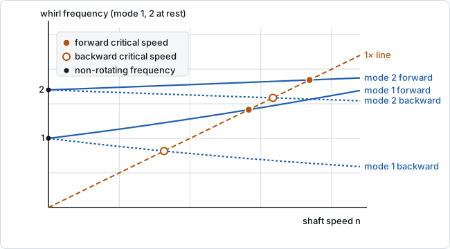
Unbalance turns with the shaft, so on round supports it excites forward whirl only. When any part has polar inertia, the critical speed check therefore uses the first forward synchronous critical speed (basis: "forwardWhirl"); otherwise the first non-rotating one. On supports stiffer in one plane than the other the whirl orbits are elliptic and the two planes are solved together, coupled by the gyroscopic matrix; there any whirl with a forward share of at least 5 % counts, elliptic backward whirl included.
The electric motor template shows the split:
| Electric motor template | First bending critical speed |
|---|---|
| Non-rotating | 27 941 rpm |
| Forward synchronous whirl | 29 023 rpm (governs the check) |
| Backward synchronous whirl | 26 926 rpm |
Unbalance response
A load's unbalance U (g·mm, the part's mass times the offset of its centre of mass) turns into a rotating force . The app solves in each bending plane at each speed from standstill to 1.3 times the highest critical speed, with structural damping ζ (Vibration damping (fraction of critical), 0.02 by default) on the shaft, supports and housings. At resonance the amplitude rises to roughly = 25 times its quasi-static value. The result unbalanceResponse gives the orbit radius (µm) at each support and unbalanced load, with its peak and the speed of the peak.
The speeds are an even grid of 120 steps with closer ones round each critical speed, plus the synchronous critical speeds that unbalance excites (with gyroscopic parts they lie above the non-rotating ones). Around each peak of each point's curve the grid is then refined: the two intervals beside the peak are halved until the speeds on either side are within 10⁻⁴ of it. For a single mass on a spring with this damping the radius is , and , which peaks at with ; the reported peak matches that within 1.3·10⁻⁵ whatever the grid, where the even grid alone missed it by 2 % at ζ = 0.02 and by 49 % at ζ = 0.002. The peak's speed is known to about , 0.03 % at ζ = 0.02, for the curve is flat at its top.
ISO 21940-11 states balance quality as a grade G (mm/s), the product of the permissible specific unbalance and the angular speed. The permissible residual unbalance follows as
with U in g·mm, G in mm/s, m in kg and n in rpm.
For the 8 kg gear of the gearbox shaft at 950 rpm and grade G 6.3, U = 9549·6.3·8/950 = 507 g·mm, a centre offset of 63 µm. With that unbalance (--unbalance 507) the orbit at the gear peaks at 1268 µm at 32 289 rpm, just above the first critical speed of 32 200 rpm (the forward whirl, stiffened by the shaft's own polar inertia), while the rigid supports stay at zero.
Torsional and axial modes
The full results (axm solve --detail) also give the torsional and axial modes. Torsion models the shaft as a rod of elements with stiffness and the polar inertia of shaft and parts, free at both ends; the rigid-body rotation is left out. The electric motor's first torsional mode is at 80 789 rpm (1346 Hz). Axially the shaft is a rod of with the parts' masses, held at the locating support by its bearing's axial tangent stiffness at its load, or rigidly when no bearing gives one (axialModesNote says so).
Magnetic pull: a negative spring
An electric machine's rotor sits in an air gap. If it moves off centre the gap narrows on one side and the magnetic pull grows towards it: a force proportional to the displacement, but pointing away from the centre. That is a spring with negative stiffness, which lowers every critical speed and, if it exceeded the stiffness of shaft and supports, would pull the rotor into the stator.
In the electric motor template the rotor's magnetic stiffness is 25 350 N/mm and its static pull at 10 % eccentricity 1267.5 N. The check reports that this negative stiffness is 10 % of what the shaft and its supports hold. It lowers the non-rotating critical speed from 29 472 rpm (pull removed: the rotor as a mass with its inertia) to 27 941 rpm, close to the estimate √(1 − 0.10) = 0.95 of a single-mode model. The negative springs carry no damping in the unbalance response.
Axial thermal growth
With thermalGrowth set, the shaft grows against the housing by from the assembly temperature. A floating bearing must take that travel. Two locating bearings (an X or O pair) make the axial problem statically indeterminate: the growth changes their axial force by , adding preload face to face and taking it off back to back.
Limits of the model
- The vibration analyses take each bearing's stiffness at its load, without its speed dependence.
- Damping is structural and proportional; fluid-film bearings and seals are not modelled.
criticalSpeedsare always the non-rotating values; the whirl results add the gyroscopic effect.- A housing enters as springs, or as the seat stiffness of a housing modelled by finite elements.