Shaft deflection calculation
A shaft is a beam on elastic supports. How far it bends decides whether gears mesh properly, and how much it tilts at a seat decides whether a bearing runs square. The support reactions are the loads the bearings have to carry.
Axomek models the stepped shaft with Timoshenko beam elements, which include shear deformation, and solves both bending planes. It gives the deflection, slope, bending moment and nominal stress along the shaft and the load and tilt at each support, and checks them against the limits you set.
What Axomek calculates
You enter
- Sections: outer diameter, bore and length of each step
- Supports: position, locating or floating, and optional radial and tilt stiffness (empty is rigid and free to tilt)
- Loads: forces in y, z and x, torque, applied moments, and the part’s mass for its weight
- Material: Young’s modulus and Poisson’s ratio (210 000 MPa and 0.3 for steel in the templates)
- Limits: maximum deflection, maximum tilt at bearings, maximum von Mises stress
- Options: shaft weight and gravity direction, coupling to the linked bearings’ non-linear stiffness, axial thermal growth
It calculates
- Deflection and slope along the shaft in the xy and xz planes, and the largest resultant deflection
- Bending moment in both planes, and the nominal von Mises stress from bending, axial force and torsion
- Radial and axial load and tilt at each support, and with coupling each bearing’s stiffness and moment
- Stiffness at each load (load over deflection) and the shaft mass
- Pass or fail for deflection, tilt at bearings and stress against your limits
Method and standards
- Timoshenko beam elements with the shear parameter φ = 12·E·I/(κ·G·A·l²); shear can be switched off for a pure bending (Euler–Bernoulli) result
- Supports as rigid constraints or linear springs in radial direction and tilt
- Optional coupling: each linked bearing follows its non-linear radial and tilt stiffness, solved by Newton’s method, with the support’s own stiffness in series as the housing
- Bending, axial force and torsion combined into the nominal von Mises stress
- The bending-only deflection of the simple shaft template matches the textbook F·L³/(48·E·I)
Limits
- Nominal stresses only: stress concentrations at shoulders and grooves are left to the strength check (DIN 743 or FKM)
- Without coupling, bearings see only forces; the supports are rigid or the springs you give
- A housing enters as springs, or as the seat stiffness of a housing modelled by finite elements
- Permissible tilt values depend on the bearing; the maker’s catalogue governs
Worked example
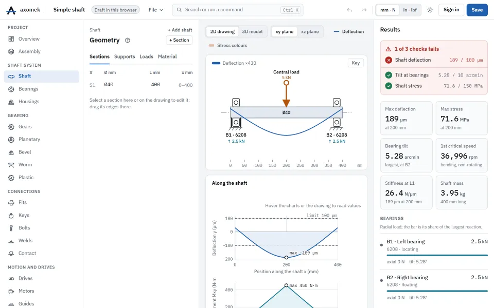
The simple shaft example: a Ø40 × 400 mm steel shaft on a locating support at x = 20 mm and a floating one at x = 380 mm, loaded with Fy = −5000 N at x = 200 mm. The limits are 0.1 mm deflection, 10 arcmin tilt at the bearings and 150 MPa von Mises stress.
| Result | Value |
|---|---|
| Maximum deflection | 0.1892 mm |
| Deflection limit | 0.10 mm |
| Maximum bending moment | 450 N·m |
| Largest tilt at a bearing | 5.276 arcmin |
| Radial load at B1 | 2,500 N |
| Maximum von Mises stress | 71.6 MPa |
| Stiffness at the load | 26.43 N/µm |
The deflection check fails against the 0.1 mm limit while tilt and stress pass; deflection falls with the fourth power of the diameter, so a modestly larger shaft brings it within the limit.
The numbers come from the engine: the same commands, run with the axm command line, give them.
The same with the axm command line
axm new ex.axm.json --template simple
axm solve ex.axm.json --jsonQuestions
Does the deflection include shear?
Yes. The Timoshenko elements add shear deformation, which matters for short, thick sections. axm apply x.axm.json '{"op":"setSettings","shearDeformation":false}' switches it off for a bending-only result.
Can the bearings’ own stiffness be included?
Yes. With Couple linked bearings each support linked to a bearing follows that bearing’s non-linear radial and tilt stiffness from its internal load distribution, so loads shift towards the stiffer bearing and bearings that resist tilt pick up moments.