Shaft critical speed calculation
A shaft running near one of its natural frequencies resonates: a small unbalance then grows into a large whirl that loads the bearings and can destroy the machine. The critical speed calculation finds those frequencies so that the running speed can be kept well clear of them.
Axomek computes the critical speeds from the same Timoshenko beam model as the deflection, with the parts’ masses and inertias and the support or bearing stiffness. For a turning shaft it adds the gyroscopic effect, which splits each mode into forward and backward whirl, and draws the Campbell diagram.
- ISO 21940-11
What Axomek calculates
You enter
- The shaft model: sections, supports with optional radial and tilt stiffness, and loads
- Part mass, polar and diametral inertia and length of each gear, pulley, coupling or rotor
- Part unbalance in g·mm, for example from an ISO 21940 balance grade
- Vibration damping as a fraction of critical (0.02 by default)
- Minimum first critical speed for the check
- Optionally: coupling to the bearings’ tangent stiffness, and a rotor’s magnetic pull as a negative spring
It calculates
- The first three bending critical speeds of the non-rotating shaft, with their mode shapes
- Forward and backward synchronous whirl critical speeds, and the Campbell diagram over the shaft speed
- The governing critical speed (forward whirl when a part has polar inertia) and its check against the minimum
- Unbalance response: orbit radius at each support and unbalanced part from standstill to 1.3 times the highest critical speed
- Torsional modes (free at both ends) and axial modes (held by the locating bearing’s axial stiffness)
Method and standards
- Generalised eigenproblem K·q = ω²·M·q with Timoshenko elements and the consistent translational and rotary mass matrix
- Parts as point masses with diametral inertia, or spread over their length at three Gauss points
- Gyroscopic whirl by replacing the rotary inertia with Id − s·Ip: s = +1 forward, s = −1 backward, a sweep of s for the Campbell diagram
- Supports stiffer in one plane than the other: both planes solved together, coupled by the gyroscopic matrix (elliptic whirl)
- Unbalance response from (K + 2i·ζ·Kd − Ω²·M)·u = U·Ω² with structural damping
- Critical speeds checked against ROSS 3.0, an independent open-source rotordynamics program, in
axm verify
Limits
- Bearings and supports are linear springs at one operating point; the speed dependence of bearing stiffness is not included
- Damping is structural, one ratio for shaft, supports and housings; fluid-film bearings and seals are not modelled
- No stability (logarithmic decrement) analysis
- Torsional modes are for the shaft alone: a motor or driven machine beyond a coupling counts only when modelled as a part
- Rigid supports make the critical speeds an upper bound
Worked example
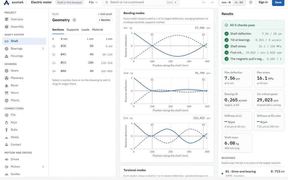
The electric motor example: a 15 kW induction motor shaft, 400 mm long (Ø38 to Ø55 mm), on a 6309 locating bearing at x = 100 mm and a 6208 at x = 380 mm, with a 20 kg Ø150 × 160 mm rotor at x = 240 mm in a 0.5 mm air gap (10 % static eccentricity) and a 2 kg coupling at x = 40 mm. It runs at 1460 rpm and must keep its first critical speed above twice that.
| Result | Value |
|---|---|
| Governing critical speed (1st forward whirl) | 29,023 rpm |
| Minimum first critical speed | 2,920 rpm |
| 1st bending critical speed, non-rotating | 27,941 rpm |
| 1st backward whirl | 26,926 rpm |
| 2nd forward whirl | 79,462 rpm |
| 1st torsional mode | 80,789 rpm |
| Rotor magnetic stiffness (negative spring) | 25,350 N/mm |
| Magnetic stiffness over the shaft and support stiffness | 10 % |
The rotor has polar inertia, so the check uses the forward whirl critical speed, which the gyroscopic effect lifts above the non-rotating value; the magnetic pull lowers all of them.
The numbers come from the engine: the same commands, run with the axm command line, give them.
The same with the axm command line
axm new ex.axm.json --template electric-motor
axm solve ex.axm.json --detail --jsonQuestions
Which critical speed does the check use?
The first forward synchronous whirl critical speed when any part has polar inertia, since unbalance excites forward whirl; otherwise the first non-rotating bending critical speed. The check’s message says which one it used.
How far should the running speed be from the critical speed?
A common design rule keeps a stiff shaft below about 70 % of its first critical speed. The electric motor example asks for at least twice its running speed.