Shaft strength calculation (DIN 743)
A shaft rarely fails on its plain sections. It fails at a shoulder, a keyway, a groove or the edge of a press fit, where the local stress is raised, and usually by fatigue long before its static strength is reached. DIN 743 turns the nominal stresses at such a section into a fatigue safety and a static safety that you compare with a required minimum.
Axomek takes the section forces from its shaft solution, checks every diameter step as a shoulder, each notch you add and the most stressed plain section, and reports both safeties at each point. With a duty cycle the checks take the worst load case.
- DIN 743-1:2012
- DIN 743-2:2012
- DIN 743 Beiblatt 1:2024
What Axomek calculates
You enter
- The shaft: sections, supports and loads (forces, moments, torque), and optionally a duty cycle
- Material: a preset steel (C45 +QT to E335) or your own σB and σS at their reference diameter, and the size-effect class for K1
- Surface roughness Rz, fillet radius at the steps and an optional surface treatment (nitrided, case hardened, deep rolled, shot peened and others)
- Notches: keyway, two keyways, groove, retaining-ring groove, V-notch, cross bore, press fit, shoulder radius or plain section, each at its position
- Torque amplitude, peak load factor for the static check, rotating or non-rotating bending, and mean stress case 1 or 2
- Minimum fatigue and static safety (1.2 by default)
It calculates
- Fatigue safety S and static safety at every shoulder, notch and the most stressed plain section
- Nominal bending, torsion and axial stresses at each point
- Stress concentration factor α, notch factor β, total influence factor K and the component fatigue limits
- Amplitude strength σADK after the mean stress, and the material strengths at the effective diameter
- The incipient crack safety of a hard surface layer, as part of the static safety
- Pass or fail against the minimum safeties, with the governing point and load case
Method and standards
- Nominal stresses from the section forces, DIN 743-1, 4.2 and Table 1; on a rotating shaft the bending moment is a fully reversed amplitude
- Notch factors β = α/n from the stress gradient for shoulders, round grooves and cross bores (DIN 743-2, 4.3); measured factors for keyways, press fits, V-notches and retaining-ring grooves (4.2), scaled by K3
- Size factors K1(deff) and K2(d), roughness factor KF and surface factor KV from the lower bounds of Table 4 (DIN 743-2, clauses 6 to 8)
- Total influence factor Kσ, Kτ and component fatigue limits, DIN 743-1, eqs. (5) to (9)
- Mean stress case 1 (constant mean) or case 2 (constant ratio, the default), with the compression zone of Annex A for compressive mean stresses
- Fatigue safety by eq. (2), static safety by eq. (25) against the component yield point, and the incipient crack check of 5.1.2 for hard layers
axm verifyrecomputes the three worked examples of DIN 743 Beiblatt 1
Limits
- Splined and serrated shafts (DIN 743-2, 4.2.2) are not among the notch kinds
- An endurance-limit check: with a duty cycle the worst load case governs, with no damage accumulation (use the FKM method for that)
- DIN 743-3 material tables are not built in beyond the seven preset steels; enter σB and σS for other steels
- Nominal stress approach only; KV is always the lower bound of the table
- Cross bores up to 2r/d = 0.3, V-notches for t/d from 0.05 to 0.2
Worked example
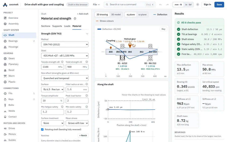
The drive shaft example: a 420 mm 42CrMo4 +QT output shaft (σB 1100 MPa, σS 900 MPa at Ø16 mm, Rz 6.3 µm, fillet radius 1.6 mm) with a helical gear at x = 197 mm passing 525 N·m to a coupling at x = 40 mm. Keyways, a retaining-ring groove, a press-fit edge and a relief groove are checked with a 10 % torque amplitude, a peak load factor of 2 and a duty cycle of Nominal 60 %, Peak 5 % (loads × 1.6) and Part load 35 % (loads × 0.5).
| Result | Value |
|---|---|
| Fatigue safety, worst load case | 6.55 |
| Minimum fatigue safety | 1.2 |
| Static safety, worst load case | 5.19 |
| Fatigue safety at the gear keyway, nominal load | 10.46 |
| Notch factor βσ at the gear keyway | 2.949 |
| σB at the effective diameter | 916.7 MPa |
| σS at the effective diameter | 703.9 MPa |
The gear keyway governs fatigue, where the bending moment is largest; the Ø45 mm coupling seat governs the static safety, as the full torque passes through the smallest diameter.
The numbers come from the engine: the same commands, run with the axm command line, give them.
The same with the axm command line
axm new ex.axm.json --template drive-shaft
axm solve ex.axm.json --jsonQuestions
Which load case does the DIN 743 check use with a duty cycle?
The worst one. DIN 743 is applied here as an endurance-limit check without damage accumulation; for finite life and load spectra switch the method to the FKM guideline and give a number of load cycles.
At which diameter are the material strengths taken?
The strengths you enter hold at their reference diameter (16 mm by default). The technological size factor K1 of DIN 743-2, 6.2, reduces them to the largest diameter of the shaft, and the results note gives the values used.