Parallel key and spline calculation (DIN 6892, DIN 5480)
A parallel key or an involute spline carries torque from a shaft to a hub by form. The flanks that touch must not be pressed beyond what the softest part can take, and the torque peaks of the machine and the uneven load along a long hub make that pressure higher than the nominal torque suggests.
Axomek picks the DIN 6885-1 key and keyway for the shaft diameter and checks the flank pressure on shaft, hub and key after DIN 6892, on the heights the key bears in the shaft groove and in the hub. For a spline it checks the flank pressure and the tooth shear, and for DIN 5480 it also gives the tip, root and form diameters and the dimensions over and between pins.
- DIN 6892
- DIN 6885-1:1968
- DIN 5480-1:2006
- DIN 5480-2:2006
- ISO 4156
What Axomek calculates
You enter
- Parallel key: shaft diameter (6 to 500 mm), hub length, form A or B, one key or two at 180°, or a special key width and height
- Spline: DIN 5480 (30°) or ISO 4156 (pressure angle 30°, 37.5° or 45°), module, number of teeth and engaged length
- DIN 5480 reference diameter dB and measuring pin diameters
- Nominal torque, application factor KA and load peak factor Kλ (or the estimate)
- Support factor fS for shaft and hub
- Shaft, hub and key materials with their yield strength
It calculates
- DIN 6885-1 key b × h, keyway depths t1 and t2 with tolerances, and the standard length range
- Flank pressure at KA·T
- Safeties of the shaft, hub and key flanks, and of the spline teeth in shear
- Torque capacity: the nominal torque at which the lowest safety reaches 1
- DIN 5480 profile shift, tooth thickness, tip, root and form diameters, dimensions over and between pins, base tangent length
Method and standards
- Key: p = 2·T·KA·Kλ/(d·h′·ltr·i·φ) as in DIN 6892, ltr = l − b for form A and l for form B
- Load-bearing heights from the keyway: h′ = t1 − c − s in the shaft and h − t1 + c − s in the hub, with the chord height c = d/2 − √(d²/4 − b²/4) of the shaft circle at the key’s flanks and the key chamfer s (r1 max of DIN 6885-1); close to method C’s 0.45·h for DIN 6885-1 keyways, and following a custom groove depth
- Two keys share the load with φ = 0.75
- Kλ estimated after DIN 6892 Fig. 5 unless given: 1 up to a bearing length of one diameter, then +0.4 per further diameter
- Flank pressure against fS·Re for shaft and hub, each on its own height, and Re for the key at the higher pressure
- Spline: pressure on the mean flank diameter with a flank overlap of 0.9·m, 0.8·m or 0.7·m and 75 % of the teeth carrying; tooth shear at the pitch circle against Re/√3
- DIN 5480 geometry from the reference profile of DIN 5480-1 and the inspection dimensions computed from the involute as tabulated in DIN 5480-2, checked in
axm verifyagainst the printed tables
Limits
- Static checks at the peak torque KA·T only: fretting, wear and fatigue under reversing torque are not assessed
- DIN 6892 method A and the shaft strength proof of method B are not included, nor taper keys, Woodruff keys or polygon profiles
- ISO 4156 splines are rated for flank pressure and shear only; the dimensions are computed for DIN 5480
- The keyway as a notch in the shaft is assessed separately, in the shaft strength check
Worked example
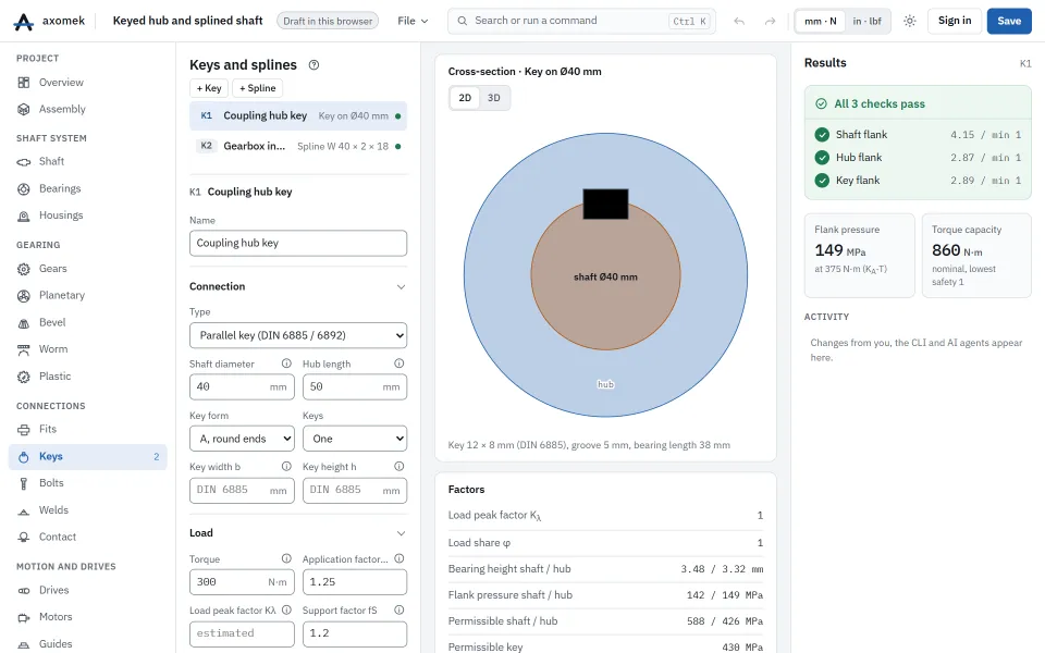
The keyed hub and splined shaft template: a form A feather key on a Ø40 mm C45 +QT shaft in a 50 mm S355 hub with a C45 +C key, and a DIN 5480 W 40 × 2 × 18 spline engaged over 40 mm, both at 300 N·m with KA 1.25.
| Result | Value |
|---|---|
| Key, flank pressure at KA·T | 148.6 MPa |
| Key, shaft flank safety | 4.15 |
| Key, hub flank safety | 2.87 |
| Key, key flank safety | 2.89 |
| Key, torque capacity | 860 N·m |
| Spline, flank pressure at KA·T | 20.9 MPa |
| Spline, tooth shear safety | 21.7 |
| Spline, torque capacity | 6,118 N·m |
The hub is the weak part of the key joint: S355 allows 1.2 × 355 MPa. The spline carries several times the key’s torque on the same diameter.
The numbers come from the engine: the same commands, run with the axm command line, give them.
The same with the axm command line
axm new ex.axm.json --template keyed-joints
axm solve ex.axm.json --jsonQuestions
Why do two keys not carry twice the torque of one?
Two keys at 180° never share the load exactly, so the pair is taken to carry 1.5 times one key (load share φ = 0.75).
Does a longer hub always help?
Only up to about one shaft diameter of bearing length. Beyond that the load peak factor Kλ rises, because the torque concentrates at the end where it comes in.