Bolted joint calculation (VDI 2230)
A preloaded bolt is a stretched spring clamping a compressed one. VDI 2230 Part 1 turns that picture into a step-by-step calculation: how much preload the joint needs, how much the bolt can take when it is tightened, the torque that gives it, and whether the bolt, the clamped parts and the interface hold under the working load.
Axomek works through the steps R0 to R13 for one bolt with its clamped plates and the loads that bolt carries, concentric or eccentric, and shows the result as checks against your required safeties, with the joint diagram and a section through the joint.
- VDI 2230-1:2015
- ISO 898-1:2013
What Axomek calculates
You enter
- Thread M4 to M36 (coarse, fine pitches through the CLI) and property class 4.6 to 12.9 after ISO 898-1
- Through bolt with nut or tapped thread, hexagon or socket head, head bearing and hole diameters, shank sections
- Clamped plates from head to nut with thickness and material, the interface diameter DA and roughness Rz
- Thread and head friction, tightening method (torque, angle or yield controlled) and tightening factor αA
- Loads per bolt: axial working load range, transverse load with plate friction, torque about the axis, least clamp load
- Load introduction factor n, entered or from Table 2 (SV 1 to SV 6)
- Optional eccentric clamping and loading with working moments, load cycles, thread engagement and temperatures
It calculates
- Resiliences of bolt and plates, load factor Φn (Φen* when eccentric) and the additional bolt load
- Preload lost to embedding and, with temperatures, the thermal change
- Required clamp load FKerf, FMmin, FMmax and the permissible assembly preload FMzul
- Tightening torque MA
- Safeties against yield in service, fatigue, surface pressure under head and nut, slipping and shearing
- Least length of thread engagement, and opening of the interface for eccentric joints
Method and standards
- R1 to R2: αA from the tool; FKerf = max(FKQ, FKP + FKA) for friction grip, sealing and opening
- R3: bolt resilience as cylinders in series (Eq. 18 to 31), plate resilience by the deformation cone and sleeve (Eq. 39 to 53), Φn = n·δP/(δS + δP)
- R4 to R6: embedding from Table 5, thermal change (R4/2), FMmin and FMmax = αA·FMmin
- R7 and R13: FMzul at ν·Rp0.2 with the thread torsion, and the torque for it at the least friction values
- R8 to R10: working stress with kτ = 0.5, stress amplitude against σASV = 0.85·(150/d + 45) or σASG, surface pressure against pG
- R11 to R12: length of engagement (Eq. 199 to 213), slip safety from the least residual clamp load and shearing against τB from Table 7
- Eccentric joints with the bending resiliences, Φen* (R3/4) and partial opening after Annex D; checked in
axm verifyagainst the five calculation examples of Annex B
Limits
- One bolt at a time: the load distribution within a multi-bolt joint (VDI 2230 Part 2) is yours to work out
- Metric threads M4 to M36 only; stainless (ISO 3506) and non-ferrous bolts are not in the property class list
- R0, choosing the nominal diameter, is left to you; the app checks the thread you give
- Relaxation and creep beyond the embedding of Table 5 are not modelled, and the preload-dependent temperature term of Eq. 117 is noted but not applied
- Hydraulic, torsion-free tightening is not covered
Worked example
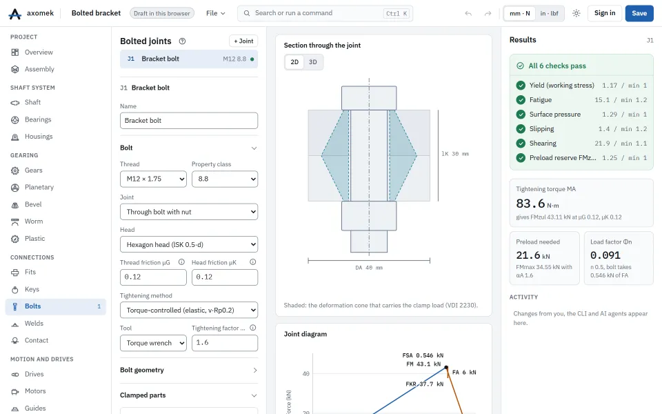
The bolted bracket template: an M12 property class 8.8 through bolt with a hexagon head on two 15 mm steel plates, DA 40 mm, μG = μK = 0.12, a torque wrench (αA 1.6), n = 0.5, and per bolt an axial working load of 6000 N and a transverse load of 2000 N at a plate friction of 0.15.
| Result | Value |
|---|---|
| Tightening torque MA | 83.6 N·m |
| Load factor Φn | 0.091 |
| Largest assembly preload FMmax | 34.6 kN |
| Permissible assembly preload FMzul | 43.1 kN |
| Yield safety (minimum 1) | 1.17 |
| Fatigue safety (minimum 1.2) | 15.1 |
| Surface pressure safety (minimum 1) | 1.29 |
| Slip safety (minimum 1.2) | 1.40 |
Slip and yield are the closest checks, almost level against their minimums: the yield check takes the full FMzul, at which the assembly stress reaches 90 % of the yield strength, and the slip check is set by the transverse load.
The numbers come from the engine: the same commands, run with the axm command line, give them.
The same with the axm command line
axm new ex.axm.json --template bolted-bracket
axm solve ex.axm.json --jsonQuestions
Why does the bolt see so little of the working load?
The clamped plates are much stiffer than the slender bolt, so most of the axial load only relieves the plates. The load factor Φn is the share that reaches the bolt; in the template it is below 10 %.
Can it rate a whole bolt pattern?
No. Each joint is a single bolt with its own loads. Work out the largest load per bolt of the pattern, including the share of any moment, and enter that.