Bolted joints (VDI 2230)
The systematic calculation of a highly stressed single-bolt joint after VDI 2230 Part 1 (2015): the steps R0 to R13, resiliences and load factor, preload losses, tightening, the stress checks, slip, thread engagement, temperature and eccentric loading.
- VDI 2230 Part 1:2015
- ISO 898-1:2013
A preloaded bolted joint works because the bolt is a stretched spring and the clamped parts are a compressed one. The working load does not add one-to-one to the bolt force: most of it only relieves the clamped parts, and the bolt sees a small fraction. VDI 2230 Part 1 turns this picture into a step-by-step calculation, R0 to R13, which the app follows for a single bolt with concentric or eccentric clamping and loading.
The joint diagram
Tightening stretches the bolt by fSM and compresses the clamped parts by fPM under the same assembly preload. Their elastic resiliences, δS for the bolt and δP for the clamped parts (deformation per unit force, mm/N), are the inverse slopes of the two lines in the joint diagram.
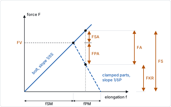
An axial working load FA stretches bolt and plates further by the same amount. The bolt takes the additional load , the clamped parts are relieved by (R3/1, R3/2), and the residual clamp load FKR is what keeps the interface closed. For a load introduced at the head and nut faces . In a real joint the load enters somewhere inside the clamped parts; the load introduction factor n (0 < n ≤ 1, section 5.2.2) accounts for that (R3/3, for concentric clamping and loading):
A stiff bolt in soft plates, or a load introduced near the head, gives a large Φ: more of the alternating load reaches the bolt.
Resiliences
- Bolt (5.1.1, Eqs. 18 to 31): the bolt is a chain of cylinders in series, : the head (a substitutional length of 0.5·d for a hexagon head, 0.4·d for a socket head), the shank sections, the free loaded thread and the engaged thread on the minor diameter, and the nut (0.4·d) or the tapped thread (0.33·d, with the tapped part's modulus).
- Clamped parts (5.1.2, Eqs. 39 to 53): the preload spreads from the head bearing diameter dW through a deformation cone whose angle follows from the ratio of the outer diameter of the clamped parts to dW (Eq. 42 for tapped, Eq. 43 for through-bolted joints). The cone widens until it reaches the outer diameter DA of the clamped parts; beyond that a sleeve of diameter DA continues, and a joint with DA ≤ dW is a sleeve alone. The body is split at the plate faces, so each plate takes its own modulus.
The load introduction factor
n is 0.5 when nothing better is known (loadIntroduction). VDI 2230 Table 2 gives it for six basic joint types SV 1 to SV 6, by the distance ak of the load introduction from the edge of the preloaded area and the length lA of the connecting solid, both relative to the joint height h; the app interpolates it from loadIntroductionCase. For a tapped joint the extra resilience δPZu of the tapped part enters the numerator (Eqs. 80 to 83).
The calculation steps
| Step | What it determines |
|---|---|
| R0 | Nominal diameter, roughly from Table A7, and the limiting size G of the interface for which the eccentric-joint relations stay valid. |
| R1 | Tightening factor , the scatter of the tightening method (Table A8: about 1.4 to 1.6 for a torque wrench, 1 for yield- or angle-controlled tightening). |
| R2 | Required clamp load : friction grip for the transverse load and torque, , sealing pressure FKP, and the clamp load against opening FKA. |
| R3 | Load factor Φ, resiliences δS and δP, and the split of FA into FSA and FPA. |
| R4 | Preload changes: loss by embedding (R4/1, fZ from Table 5) and the thermal change ΔF′Vth (R4/2). |
| R5 | Minimum assembly preload (R5/1). |
| R6 | Maximum assembly preload (R6/1). |
| R7 | Permissible assembly preload FMzul at the utilisation ν of the yield strength, and the check (R7/3). |
| R8 | Working stress: the bolt under FMzul plus FSA with part of the tightening torsion, against Rp0.2. |
| R9 | Alternating stress amplitude against the bolt's fatigue limit. |
| R10 | Surface pressure under head and nut against the limiting pressure pG. |
| R11 | Minimum length of thread engagement, so that the bolt breaks before the thread strips. |
| R12 | Safety against slipping and shearing. |
| R13 | Tightening torque MA. |
Assembly preload (R7) and tightening torque (R13)
During torque tightening the bolt carries tension and the torsion of the thread friction. FMzul is the preload at which their von Mises combination reaches ν·Rp0.2 (ν = 0.9 by default, utilisation), R7/2:
with the weakest cross-section A0 and its diameter d0 (stress diameter, reduced shank or the bore of a hollow bolt), the pitch diameter d2, the pitch P and the least thread friction μG,min. The torque that produces it, R13/1, is
with the mean bearing diameter and the least head friction μK,min. Using the least friction values is deliberate: with higher actual friction the preload is lower, which R5 and R6 already cover through αA.
Working stress (R8)
In service the bolt load reaches (R8/1). The tightening torsion partly relaxes; VDI 2230 recommends keeping kτ = 0.5 of it (R8/4):
Alternating stress (R9)
The stress amplitude in the thread is (R9/1), against the fatigue limit for 2·10⁶ cycles of a bolt rolled before heat treatment, (R9/5-1), or the higher σASG of a thread rolled after heat treatment (R9/5-2). For fewer cycles the limit rises by or (R9/6). VDI 2230 recommends .
Surface pressure (R10), engagement (R11), slip and shear (R12)
Surface pressure: the larger of FMzul and the working state's bolt load over the bearing area Ap under head and nut, against pG (R10/1, R10/2). VDI 2230 Table A9 lists pG for common materials.
Engagement: the strength ratio of bolt and nut thread and the least length of engagement with the factors C1 to C3 for nut dilation and thread bending (Eqs. 199 to 213).
Slip: the least residual clamp load (R12/1)
over the clamp load FKQ needed for the transverse load gives SG (R12/4). VDI 2230 suggests SG ≥ 1.2 for static and 1.8 for alternating transverse load. If the joint slips anyway, the bolt must not shear: against from Table 7 (R12/5 to R12/7).
Temperature
When bolt and clamped parts warm by different amounts, or expand differently, the preload changes (R4/2):
with the moduli at room and at operating temperature. A positive value is a loss: it is added to FMmin and taken from the residual clamp load. An aluminium flange clamped by a steel bolt gains preload when warm and loses it when cold.
Eccentric clamping, working moments and opening
When the bolt axis is offset from the axis of the deformation body (ssym) or the load acts off the bolt axis (distance a), the plates bend as well as compress. VDI 2230 then uses the bending resiliences of bolt and plates (Eqs. 59 to 72) and the eccentric load factor Φen* (R3/4). FKA (R2/3) becomes the clamp load that keeps the interface edge at risk (distance u) from opening; above the opening limit FAab (Eq. 104) the joint opens partially and the additional bolt load rises steeply along the lever of edge bearing. The app models that range by the circular arc of Annex D and adds the bolt bending stress σSAb (Eqs. 184 to 189) to the alternating stress. An external working moment MB (with eccentric) enters FKA, FAab, the opening moment MBab and the bolt bending.
A worked example
The Bolted bracket template: M12, property class 8.8 (Rp0.2 640 MPa, Rm 800 MPa), two 15 mm steel plates, DA = 40 mm, μG = μK = 0.12, αA = 1.6, n = 0.5, FA = 6000 N axial and FQ = 2000 N transverse per bolt, μT = 0.15.
| Step | Result |
|---|---|
| R2 | FKerf = 2000/0.15 = 13 333 N |
| R3 | δS = 2.769·10⁻⁶ mm/N, δP = 0.616·10⁻⁶ mm/N, Φn = 0.091, FSA = 546 N |
| R4 | fZ = 9.5 µm, FZ = 2806 N |
| R5 | FMmin = 13 333 + 0.909·6000 + 2806 = 21 594 N |
| R6 | FMmax = 1.6·21 594 = 34 550 N |
| R7 | FMzul = 43 110 N ≥ FMmax (80 %) |
| R8 | σred,B = 547.3 MPa, SF = 1.169 |
| R9 | σa = 3.24 MPa, σASV = 48.9 MPa, SD = 15.09 |
| R10 | p = 588.2 MPa against pG = 760 MPa, Sp = 1.292 |
| R12 | FKR,min = 18 683 N, SG = 1.401; shear safety 21.91 |
| R13 | MA = 83.59 N·m |
The low Φ of 0.091 is typical of a slender bolt in thick steel plates with n = 0.5: of the 6000 N working load only 546 N reach the bolt, which is why the fatigue safety is so high. The joint is governed by friction grip: slip safety 1.401 against 1.2.
axm new bracket.axm.json --template bolted-bracket
axm solve bracket.axm.json
What is not covered
- Multi-bolt joints are rated one bolt at a time: give each bolt its share of the loads.
- Relaxation and creep beyond the embedding of Table 5, and the preload-dependent temperature term of Eq. 117 (named in a note, not applied).
- Hydraulic, torsion-free tightening (5.4.4).
axm verify recomputes the five calculation examples of VDI 2230-1 Annex B.