Hertz contact and subsurface stress
Point and line contact after Hertz, the contact ellipse, curvature sum and maximum pressure, the shear stresses below the surface, the case depth rule, and the app's maxShearStress, maxShearDepth and suggestedCaseDepth.
- ISO 281:2007
- ISO 76:2006
- ISO/TS 16281:2008
- ISO/TR 1281-1:2008
Why contact stress decides
A rolling element touches each raceway over a contact area a few tenths of a millimetre wide. The whole element load passes through that small area, so the pressure there reaches 1 500 to 4 000 MPa. Almost every bearing calculation goes back to this contact: the static rating (a stress limit, ISO 76), the fatigue load limit Cu (a stress limit, ISO 281, Annex B), the load–deflection law of the load distribution, the lubricant film and the life theory of Lundberg and Palmgren, whose correlation is built on the subsurface shear stress (ISO/TR 1281-1, Clause 4).
Hertz's assumptions
Hertz's theory describes two smooth, curved, linear-elastic bodies pressed together. It assumes that the contact area is small against the radii of curvature, that the surfaces are frictionless and that there is no lubricant film. The pressure over the contact area is then semi-ellipsoidal (point contact) or semi-elliptic across a strip (line contact). The elastic constants enter through the reduced modulus
which is 227 500 MPa for two steel bodies with E = 207 000 MPa and ν = 0.3.
Curvature sum and difference
Each body has two principal curvatures at the contact, one in the rolling direction and one across it; convex counts positive, concave (a groove) negative. For a ball of diameter Dw in grooves of radius and , with (see the figure in Internal load distribution):
- inner contact:
- outer contact:
The curvature difference F(ρ), the difference of the two planes' curvatures over Σρ, sets the shape of the contact ellipse. ISO/TS 16281 writes these as Eq. (5) to (8). Conformity f close to 0.5 means a groove that hugs the ball: Σρ falls, the ellipse grows longer and the pressure drops. This is why the groove radii matter so much (see Internal load distribution).
Point contact: the contact ellipse
A ball in a groove makes an elliptical contact with semi-axes a (across the rolling direction) and b (along it). The ellipticity follows from F(ρ) through the complete elliptic integrals of the first and second kind, K and E (ISO/TS 16281, Eq. (1) to (4)). With :
- maximum pressure
The approach of the two bodies grows with , which gives the load–deflection law of balls. The app solves the ellipticity equation numerically rather than with curve-fit approximations.
For the most heavily loaded ball of the bearing-6207 template (1 118 N) the app reports:
| Contact | a | b | p0 |
|---|---|---|---|
| Inner ring (fi = 0.52) | 1.530 mm | 0.164 mm | 2 130 MPa |
| Outer ring (fe = 0.53) | 1.261 mm | 0.220 mm | 1 924 MPa |
The inner contact is the more stressed: its raceway is convex in the rolling direction, the outer one concave.
Line contact
A cylindrical or tapered roller makes a strip of half-width b along the roller. Per unit length :
A real roller is crowned, so the load per unit length varies along it. The app follows ISO/TS 16281 and cuts each roller into laminae (slices), each a short line contact with its own load and pressure. ISO 281, B.3.2.1.3 notes that plain Hertz formulas for cylinders are not adequate for profiled rollers; the lamina model with the roller profile and the edge stress factor of ISO/TS 16281 (Eq. (58) to (60)) is the app's answer to that. For the NU 207 preset at Fr = 5 000 N the centre lamina of the most loaded roller has b = 0.110 mm and p0 = 1 535 MPa.
Stresses below the surface
The contact pressure compresses the material in all three directions. At the surface the three principal stresses are similar, so the shear stress there is moderate. Below the surface the stress across the contact decays faster than the stress into the depth, and the shear stress rises to a maximum some way down. Rolling contact fatigue usually starts there, at inclusions in the steel, which is why the depth matters.
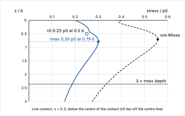
Three measures are used:
- Largest shear stress τmax (half the largest difference of principal stresses). Below a line contact it peaks at 0.300·p0 at z = 0.786·b; below a circular contact at about 0.31·p0 at z ≈ 0.48·a (ν = 0.3). It does not reverse as an element passes.
- Orthogonal shear stress τ0, the shear in the plane of rolling, τxz. It is zero below the centre and peaks off-centre, at 0.25·p0 at z = 0.5·b for line contact. As an element rolls over a point, τxz changes sign, so its range is , larger than the range of τmax. Lundberg and Palmgren built the life theory on it (ISO/TR 1281-1, 4.1 gives τ0 and its depth through an auxiliary parameter t that depends on b/a), and ISO 281, 9.3.2 mentions it as the traditional fatigue criterion.
- von Mises stress, 0.557·p0 at z = 0.70·b for line contact, useful against the yield strength.
axm verify checks the app's stress field against the closed-form values of Johnson's Contact Mechanics (§3.4 and §4.2), group "Hertz contact: subsurface stress".
What the app computes
Below the most stressed contact of every bearing the app evaluates the frictionless Hertz stress field: for line contact by the closed-form plane-strain solution, for an ellipse by integrating the point-load solution over the Hertz pressure (Gauss–Legendre quadrature), and τ0 by the Lundberg–Palmgren closed form. The bearing results give:
maxShearStress: τmax in MPa;maxShearDepth: its depth below the surface in mm;suggestedCaseDepth: 3 ×maxShearDepthin mm;- in
detail.subsurface.peaks:maxShear,orthogonalShearandvonMises, each with value and depth, and the contact (a,b,p0) and ring they belong to.
| Result | 6207 template (ellipse, a/b = 9.3) | NU 207, 5 000 N (line) |
|---|---|---|
| p0 | 2 130 MPa | 1 535 MPa |
| τmax at depth | 670.9 MPa at 0.126 mm | 460.9 MPa at 0.0864 mm |
| τ0 at depth | 530.9 MPa at 0.081 mm | 383.7 MPa at 0.055 mm |
| von Mises at depth | 1 220.8 MPa at 0.118 mm | 855.7 MPa at 0.0774 mm |
| Suggested case depth | 0.378 mm | 0.259 mm |
The roller's values sit at the classical line-contact ratios (0.300·p0 at 0.786·b; 0.25·p0 at 0.5·b). The ball's long, narrow ellipse comes close to them (τmax = 0.315·p0 at 0.77·b).
Case depth of case-hardened rings
A case-hardened ring has a hard surface layer over a softer, tougher core. The case must reach well below the depth of the largest shear stress, so that the stress has decayed to what the core can carry where the hardness drops. The app's rule of thumb asks for three times the depth of τmax. For the template that is 0.378 mm.
Enter the real case depth under Requirements as Case depth (case-hardened) (limits.caseDepth). The check bearings.<id>.caseDepth then fails when it is less than the suggested depth.
Limits
- Frictionless contact: surface traction, which moves the maximum shear towards the surface at high friction, is not included.
- No residual stresses from hardening or from the fit, no hoop stress.
- Smooth surfaces: roughness peaks and dents from particles (the subject of eC in ISO 281) are not resolved.
- Elastic material: above the yield strength, plastic flow changes the field; the static safety keeps the contact below the ISO 76 limit.