Internal load distribution (ISO/TS 16281)
How the app shares a bearing's load among its rolling elements after ISO/TS 16281: load–deflection laws, clearance and load zone, contact angle change, tilt, roller laminae and crowning, the reference load and life, and why the groove radii matter.
- ISO/TS 16281:2008
- DIN 26281:2010
- ISO 281:2007
- ISO/TR 1281-1:2008
From bearing load to element loads
ISO 281 rates a bearing with a fixed, idealised load distribution. ISO/TS 16281 goes one step further: it finds the actual load on every rolling element from the equilibrium of the inner ring, with the operating clearance, the tilt and, for rollers, the load along the roller taken into account, and computes the life from those loads. DIN 26281:2010 is its German edition, including the 2009 corrigendum; DIN ISO 281 Beiblatt 4 was its starting point. ISO/TS 16281 has since been replaced by ISO 16281:2025, whose text has not been checked; the app follows the 2008 Technical Specification.
The app solves this for every bearing, standing alone or on a shaft support. The inner ring has five degrees of freedom (axial and two radial displacements, two tilts). For a trial position each element's deflection follows from the geometry, its load from Hertz contact, and the sum of the element forces and moments must balance the applied loads. A Levenberg–Marquardt solver finds that position; for a bearing with clearance under a light load, whose solution lies slightly past the clearance, it starts at a multiple of the load and steps down in halves.
Ball bearings
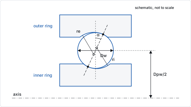
A ball touches each groove at the point where the line through the two groove curvature centres crosses it. Unloaded and without clearance, the centres are a distance apart (ISO/TS 16281, Eq. (13)). A radial internal clearance Pd lets the ball drift until both contacts close, at the free contact angle . When the inner ring moves by an axial displacement, a radial displacement and a tilt, the inner groove centre of ball j moves with it (Eq. (12), with the inner groove centre radius Ri of Eq. (14)). The new centre distance minus A is the ball's elastic deflection δj, and its direction is the new contact angle αj (Eq. (15)).
Each ball obeys the point-contact law
(Eq. (10)),
where K combines the inner and outer contacts, each from its curvature sum and ellipse (Eq. (9), (11); see Hertz contact and subsurface stress). The force acts along the contact line, and its moment is taken about the inner ring centre with the arm . The equilibrium equations are Eq. (16) to (18).
For the bearing-6207 template (Pd = 0.015 mm, grooves 0.52/0.53·Dw) the free contact angle is 9.4°, and . Under Fr = 2 500 N and Fa = 800 N the inner ring moves 0.039 mm axially and 0.016 mm radially. The ball loads are:
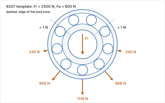
The axial load turns every loaded ball to 13.0° to 13.3°, which widens the load zone: five balls carry almost all of the load and the most loaded carries 1 118 N.
Clearance and the load zone
Clearance narrows the load zone. Without an axial load, a bearing with no clearance carries a radial load on roughly half its elements; with clearance fewer elements take it and the most loaded one carries more. An axial load works the other way in a deep groove ball bearing: it pushes the balls up the flanks, raises the contact angle and spreads the load round the ring. The template shows both effects:
| Radial clearance | Most loaded ball | pmax | Modified life |
|---|---|---|---|
| 0 | 1 105 N | 2 123 MPa | 184 681 h |
| 0.015 mm (template) | 1 118 N | 2 130 MPa | 223 847 h |
| 0.040 mm | 1 262 N | 2 215 MPa | 169 620 h |
With zero clearance the contact angle rises only to 11.1° to 11.5°, so the balls need more normal load to carry the same axial force (Pref 2 559 N against 2 475 N); a large clearance concentrates the load on fewer balls. The operating clearance after fits and temperatures can come from the bearing's mounting (see Fits).
Tilt
A bearing on its own has its inner ring held at zero tilt by default (Inner ring tilt: "Held at zero, as ISO 281 rates (no moment load)"), and the results report the moment that holds it (detail.heldMoment; −15 614 N·mm for the template). Released ("Free to tilt under the moments"), a single-row bearing under combined load tilts away from its load zone. The template then tilts by 0.0037 rad, its contact angles spread from 3.5° to 24°, pmax rises to 2 343 MPa and the modified life falls to 63 092 h. On a shaft support the tilt always comes from the shaft's slope. Self-aligning ball and spherical roller bearings take no moment and pass the slope freely.
High speed
ISO/TS 16281 neglects centrifugal and gyroscopic forces, which is fair at low and moderate speed (4.1 and 5.1). For spindles the app offers a high-speed ball model (highSpeed), in which every ball balances its inner and outer contact forces with its centrifugal force and gyroscopic moment, so the two contact angles and loads differ.
Roller bearings: laminae and crowning
Line contact gives a stiffer law,
, with for steel (Eq. (34), (35)).
Because a roller can tilt against the raceway and its load varies along its length, ISO/TS 16281 cuts it into laminae (Eq. (36), (37)). Each lamina's deflection comes from the ring displacement, the tilt and the roller profile at that slice (Eq. (38) to (41)). ISO/TS 16281 asks for at least 30 laminae (5.2.2); the app uses 41 by default (Lamina per roller) and scales the steel constant by the materials' elastic constants, so ceramic rollers deflect some 15 % less.
The profile is the logarithmic crowning of ISO/TS 16281, Eq. (42) to (44): a drop of at the distance x from the roller centre, with k = 0.00035 for rollers up to 2.5·Dw long. Edge stress applies the edge stress factor of Eq. (58) to (60) at the roller ends ("ISO/TS 16281 edge factor") or none.
With the detailed results, the app also searches the crowning coefficient that minimises the peak lamina stress under the operating load. For the NU 207 preset at Fr = 5 000 N:
| Profile | Peak lamina stress | Edge ratio |
|---|---|---|
| Straight rollers (k = 0) | 1 991 MPa | 1.53 |
| ISO/TS 16281 profile (k = 0.00035) | 1 535 MPa | 0.92 |
| Optimum (k = 0.000112) | 1 398 MPa | 1.00 |
The edge ratio is the largest stress in the outer quarters of the most loaded roller over its centre lamina's stress: above 1 means edge peaks (too little crowning), below 1 a centre peak (too much). The optimum here has a drop of 3.40 µm at the end laminae.
Spherical roller bearings have their laminae on an arc of the spherical outer raceway, each normal through the sphere's centre, so they have no tilt stiffness.
From element loads to life
The element loads give, ring by ring, a dynamic equivalent element load and with the ring's rating element load the basic reference rating life L10r (ISO/TS 16281, Eq. (25) to (29) for balls; lamina by lamina, Eq. (47) to (65), for rollers). The reference load Pref is the load that gives the same life in the ISO 281 equation (Eq. (30), (31), (66), (67)). The modified reference rating life applies a1 and aISO of ISO 281 (Eq. (32), (33); rollers Eq. (68) to (71)). Details are on Equivalent bearing load and Rating life (ISO 281).
Every row of a double-row bearing gets the life of its own element loads, and the rows combine by the Weibull rule of the system life.
Why the groove radii matter
The groove radii are usually given as conformities, and . ISO/TS 16281 uses 0.52 (inner) and 0.53 (outer) as reference values for deep groove and angular contact ball bearings (6.3, Eq. (72), (73)), and the presets use them. Small changes in f change several results at once, because the curvature sum in the groove plane depends on 4 − 1/f, and 1/f changes quickly near f = 0.5:
- Contact stress. A tighter groove gives a longer ellipse and a lower pmax under the same load.
- Stiffness. The contact constant K rises, so the bearing deflects less.
- Ratings. fc of ISO/TR 1281-1, Eq. (15) depends on the groove radii, so C rises with tighter grooves; C0 and Cu follow from the stress limits and rise too.
- Contact angle change. A tighter pair of grooves has a smaller A, so the same clearance gives a larger free contact angle and the angle moves more under axial load.
The app uses the actual radii everywhere, also for C, C0 and Cu. For the template:
| Grooves (inner/outer) | C | C0 | Cu | pmax | Radial stiffness | Basic life | Modified life |
|---|---|---|---|---|---|---|---|
| 0.52/0.53 (template) | 25 189 N | 15 298 N | 797 N | 2 130 MPa | 150 320 N/mm | 6 061 h | 223 847 h |
| 0.52/0.52 | 25 663 N | 15 298 N | 797 N | 2 151 MPa | 154 563 N/mm | 6 233 h | 224 312 h |
| 0.515/0.525 | 28 040 N | 18 191 N | 948 N | 2 030 MPa | 155 859 N/mm | 8 146 h | 407 307 h |
Tightening the outer groove alone changes C but not C0 or Cu, which are governed by the inner contact here; it also narrows the load zone a little, so pmax rises. Tightening both by 0.005 lifts the basic life by a third and, with aISO at its cap of 50, nearly doubles the modified life.
For roller bearings the conformities are not used.
Stiffness from the same model
Because the element laws are non-linear, the bearing's stiffness depends on the load. The app differentiates the element reactions at the operating point to get the 5×5 tangent stiffness matrix of the inner ring. The template's radial stiffness is 150 320 N/mm (tangent) and 160 538 N/mm (secant, load over displacement); its axial stiffness is 22 227 N/mm. A ball bearing without clearance has a tangent stiffness 1.5 times its secant stiffness, a straight roller 10/9 times.
From the command line
axm solve p.axm.json --detail --jsondetail.rows[] lists every element's loads, contactAngles, stressInner, stressOuter and, for rollers, laminaLoads; detail.displacement gives the ring's displacement and tilt; profile (roller bearings) the crowning search; stiffness.operating the matrix.