Fits: ISO 286 and press fits (DIN 7190)
ISO 286 tolerance grades and fundamental deviations, clearance, transition and interference fits, the elastic press fit of DIN 7190-1 by thick-walled cylinder theory, and how bearing seat fits change the operating clearance.
- ISO 286-1
- ISO 286-2
- DIN 7190-1
- ISO 492
A fit is the relation between a hole and the shaft in it. ISO 286 defines where the size limits of each lie; DIN 7190-1 tells what an interference between them does: how much pressure it builds, how much torque it carries and how much it stresses the hub. The same theory decides how a bearing ring's clearance shrinks when it is pressed onto its seat.
Tolerance grades and fundamental deviations
ISO 286-1 describes a size tolerance by two numbers relative to the nominal size (the zero line): an upper and a lower deviation, ES and EI for a hole, es and ei for a shaft. A tolerance class such as H7 or s6 encodes both:
- The number is the standard tolerance grade IT. It sets the width of the zone, the tolerance. The standard tolerance grows with the nominal size range and by roughly a factor of 1.6 from one grade to the next in the common grades.
- The letter is the fundamental deviation: the limit closest to the zero line, which places the zone. Capitals are holes, lower case shafts. H holes start at the zero line (EI = 0) and lie above it; h shafts end at it (es = 0) and lie below. Letters before H and h give looser fits (holes larger, shafts smaller), letters after them tighter ones. JS and js are symmetric about the zero line.
The other limit follows from the grade: for a hole , for a shaft . ISO 286-2 tabulates the fundamental deviations and tolerances; the app computes them for the hole letters F to S and shaft letters f to s in grades 4 to 7 (the inspector's lists offer the common classes from F7 to S7 and f6 to s6).
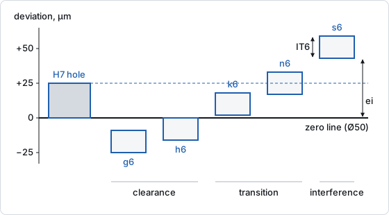
Hole basis, shaft basis and fit types
In the hole-basis system every hole is H and the shaft letter chooses the fit; in the shaft-basis system every shaft is h. Hole basis is the usual choice in machine building, because reamed or bored holes are harder to vary than turned or ground shafts.
The fit type follows from the two zones:
- Clearance fit: the hole is always larger; the smallest clearance is ≥ 0.
- Transition fit: depending on the actual sizes there is clearance or interference.
- Interference fit: the shaft is always larger; the smallest interference is ≥ 0.
The Fits module reports, for Ø50 mm with an H7 hole (0 to +25 µm):
| Pair | Shaft deviations | Clearance range | Fit type |
|---|---|---|---|
| H7/g6 | −9 to −25 µm | 9 to 50 µm | Clearance |
| H7/h6 | 0 to −16 µm | 0 to 41 µm | Clearance |
| H7/k6 | +2 to +18 µm | −18 to 23 µm | Transition |
| H7/n6 | +17 to +33 µm | −33 to 8 µm | Transition |
| H7/s6 | +43 to +59 µm | −59 to −18 µm | Interference |
A negative clearance is an interference. Only the interference fit carries load reliably by friction: a transition fit may be loose, so its least interference, and with it the transmissible torque, is zero.
The elastic press fit
DIN 7190-1 treats the shaft (index I, inner part) and the hub (index A, outer part) as thick-walled cylinders of equal length in plane stress, elastic throughout. Their geometry enters through the diameter ratios of the hub (joint diameter over outside diameter) and the shaft (bore over joint diameter, 0 for a solid shaft):
From interference to pressure
The measured interference is not all effective. Pressing flattens the roughness peaks of both surfaces, and DIN 7190-1 deducts for that smoothing. With the effective interference Z and its ratio , Lamé's solution for two cylinders gives the joint pressure
For a solid shaft and hub of the same material this reduces to . In each part the radial and hoop stresses vary as : the radial stress is −p at the joint and zero at a free surface, and the hoop stress is largest in tension at the hub bore. The result stressProfile gives both through shaft and hub.
Capacity and slip
The joint carries load by friction. Its capacity is computed from the smallest effective interference, because a joint must hold with the loosest parts the tolerances allow:
with the friction coefficient μ (friction, 0.12 by default; 0.12 to 0.15 is typical for a dry steel shrink fit) and the joint length l. The slip safety is the capacity over the torque to carry. The stresses use the largest interference.
Stresses in hub and shaft
The hub is checked at its bore with DIN 7190-1's von Mises stress
The exact plane-stress value is reported alongside as hubStressExact; at QA = 0.5 it is about 1 % higher. A solid shaft is under uniform compression p in the plane, so its equivalent stress is p. The yield safeties are the yield strengths over these stresses.
Temperatures, assembly and speed
- Operating temperatures change the interference by from the assembly temperature. The app takes the capacity from the smaller and the stresses from the larger interference of the assembly and the operating state.
- Shrink temperature: to assemble without force the hub must expand by the largest interference plus an assembly clearance, which the app takes as 0.001·d. The hub temperature is .
- Centrifugal loosening: turning, the hub bore grows more than the shaft surface (rotating thick-walled cylinders). For a solid shaft and a hub of the same material the diametral interference lost at angular speed ω is . The
looseningSpeedis where the smallest interference is used up; with aspeedthe capacity and slip safety are evaluated turning, and the hub's centrifugal hoop stress adds to its stress at the pressure left.
A worked example
The Shrink-fit hub template: Ø50 H7/s6, hub C45 +QT with DaA = 100 mm, solid 42CrMo4 shaft, l = 50 mm, Rz 4 µm on both parts, μ = 0.12, 250 N·m to carry.
| Quantity | Value |
|---|---|
| Interference from the limits | 18 to 59 µm |
| Smoothing 0.8·(4 + 4) | 6.4 µm |
| Effective interference | 11.6 to 52.6 µm |
| QA | 0.5 |
| Pressure p | 18.27 to 82.84 MPa |
| Torque capacity (at 18.27 MPa) | 430.5 N·m, slip safety 1.722 |
| Axial capacity | 17 219 N |
| Hub stress √3·p/(1 − QA²) | 191.3 MPa, yield safety 2.561 |
| Hub stress, exact | 193.3 MPa |
| Shaft stress | 82.84 MPa, yield safety 10.86 |
| Shrink temperature | 218.2 °C |
| Loosening speed | 16 565 rpm |
The pressure checks by hand: p = 210 000·(0.0526/50)·(1 − 0.25)/2 = 82.84 MPa. The torque: 0.12·18.27·π·50²·50/2 = 430 477 N·mm. The shrink temperature: 20 + (0.059 + 0.05)/(11·10⁻⁶·50) = 218.2 °C.
axm new hub.axm.json --template shrink-fit
axm solve hub.axm.json
Bearing seats and operating clearance
A rolling bearing's internal clearance changes from its unmounted value to its operating value in three steps, which the app computes when a bearing has a mounting:
- Fit: the ring bore and outside diameter follow ISO 492 (normal class), the seats ISO 286 (also grade-4 housing bores K4 to S4). The interference, less the smoothing 0.8·(Rz ring + Rz seat) with Rz 2.5 µm for the ring when a seat roughness is given, builds a fit pressure by the same thick-walled cylinder theory, with the moduli and Poisson's ratios of shaft, housing and bearing steel.
- Ring expansion and contraction: the inner ring's raceway grows and the outer ring's shrinks. For equal materials the familiar approximations are for an inner ring on a solid shaft (bore d, raceway diameter F) and for an outer ring in a thick housing (raceway diameter E, outside diameter D), with I the effective interference. The inner ring's hoop stress at the bore is reported.
- Temperature: rings, rolling elements, shaft and housing expand from 20 °C at their own temperatures; a warmer inner ring takes clearance away.
A negative operating clearance means the bearing runs preloaded, which axm validate warns about. The shaft's material and bore and the housing's material are taken from the model unless the mounting sets them.