Bearing load distribution (ISO/TS 16281)
ISO 281 rates a bearing with a fixed, idealised load distribution. In a real bearing the load zone depends on the clearance, the axial load, the tilt and, for rollers, how the load spreads along each roller. ISO/TS 16281 finds the actual load on every rolling element from the equilibrium of the inner ring and computes the life from those loads.
Axomek solves this for every bearing, on its own or on a shaft support. It gives each element’s load, contact angle and contact stress, the ring displacements and the stiffness, and passes the element loads on to the rating life and the static safety.
- ISO/TS 16281:2008
- DIN 26281:2010
- ISO 281:2007
- ISO/TR 1281-1:2008
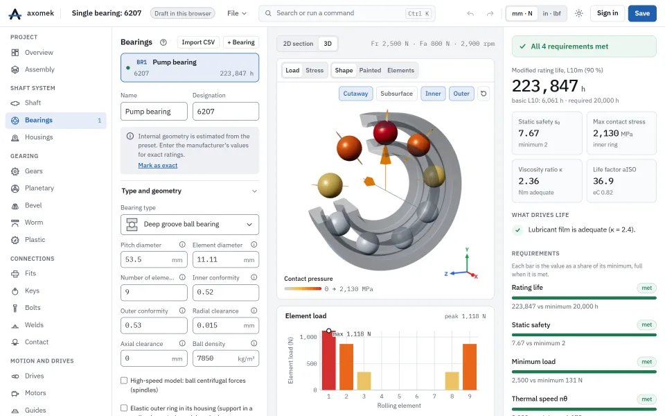
What Axomek calculates
You enter
- Bearing type and internal geometry: pitch diameter, element diameter and number, contact angle, groove radii or roller length
- Radial and axial clearance, or the operating clearance from the fits and ring temperatures
- Loads Fx, Fy, Fz and moments, or the reaction and slope of a shaft support
- Inner ring tilt: held at zero (as ISO 281 rates) or free to tilt under the moments
- For rollers: number of laminae, crowning coefficient and edge stress model
- Element and ring materials (moduli and Poisson’s ratio), and optionally the high-speed ball model
It calculates
- Load, contact angle and inner and outer contact stress of every rolling element (and every lamina of a roller)
- Largest contact stress pmax with its contact ellipse
- Inner ring displacement and tilt, and the moment that holds the ring square
- Reference load Pref and the life from the element loads
- 5 × 5 tangent stiffness matrix of the bearing at its operating point
- For rollers: the crowning that minimises the peak lamina stress, and the edge ratio
Method and standards
- The inner ring has five degrees of freedom; a Levenberg–Marquardt solver finds the position at which the element forces balance the loads
- Balls: groove centre distance A = ri + re − Dw (Eq. (13)), free contact angle from the clearance, new contact angle from the ring displacement (Eq. (12) to (15)), and Q = K·δ1.5 (Eq. (10))
- Rollers: Q = cL·δ10/9 (Eq. (34), (35)) on 41 laminae by default (at least 30, 5.2.2), with the logarithmic crowning of Eq. (42) to (44) and the edge stress factor of Eq. (58) to (60)
- Basic reference rating life from the element loads, Eq. (25) to (29) for balls and (47) to (65) for rollers, and Pref by Eq. (30), (31), (66), (67)
- Modified reference life with a1 and aISO of ISO 281, Eq. (32), (33) and (68) to (71)
Limits
- Follows the 2008 Technical Specification; its successor ISO 16281:2025 has not been checked against its text
- Centrifugal and gyroscopic ball forces are neglected, as in ISO/TS 16281, unless the high-speed ball model is switched on
- The rings are rigid unless the outer ring is taken as elastic in a modelled housing
- Truncation of the contact ellipse at the groove edge is not checked
- Fits change the clearance of deep groove ball and radial roller bearings only
Worked example
The 6207 example: a deep groove ball bearing (Dpw 53.5 mm, nine 11.11 mm balls, grooves 0.52/0.53·Dw, radial clearance 0.015 mm) under Fr = 2500 N and Fa = 800 N, with the inner ring held square.
| Result | Value |
|---|---|
| Load on the most loaded ball | 1,118 N |
| Largest contact stress pmax | 2,130 MPa |
| Contact ellipse semi-major axis | 1.530 mm |
| Free contact angle α0 from the clearance | 9.4° |
| Operating contact angle of the most loaded ball | 13.0° |
| Inner ring axial displacement | 39.0 µm |
| Inner ring radial displacement | 15.6 µm |
| Reference load Pref | 2,475 N |
The axial load turns the loaded balls well above their free contact angle, which widens the load zone and shares the radial load over more balls.
The numbers come from the engine: the same commands, run with the axm command line, give them.
The same with the axm command line
axm new ex.axm.json --template bearing-6207
axm solve ex.axm.json --detail --jsonQuestions
Why do the groove radii matter so much?
The curvature in the groove plane depends on 4 − 1/f, which changes quickly near f = 0.5. A slightly tighter groove lowers that contact’s stress under the same element load, stiffens the bearing and raises C, and also C0 and Cu when that contact governs them. Axomek uses the actual radii everywhere, so enter the maker’s values when you have them.
Does the bearing tilt on a shaft?
Yes. On a shaft support the inner ring always takes its tilt from the shaft’s slope. A bearing on its own is held square by default and reports the moment that holds it; released, a single-row bearing under combined load tilts away from its load zone.