Shaft strength to the FKM guideline
The FKM guideline is the German analytical strength assessment for machine components. For a shaft it works with the same nominal stresses as DIN 743, but states the result as degrees of utilisation with explicit safety factors, and it covers finite life and variable loads through an S-N curve and damage accumulation.
Axomek applies the guideline’s nominal stress approach to every shoulder, notch and the most stressed plain section of the shaft. Give it a number of load cycles and a duty cycle, and it shares the cycles over the load cases and accumulates the damage by the Miner rule.
- FKM guideline, 7th edition (2020)
What Axomek calculates
You enter
- The shaft, its loads and optionally a duty cycle with time shares, load factors and speeds
- FKM material group (quenched and tempered, case-hardening, structural, stainless steel, cast steel, nodular cast iron, wrought or cast aluminium) and the strengths Rm, Rp
- Safety class (consequences of failure and inspection, jF 1.2 to 1.5), probability of the peak load, and casting inspection for cast groups
- Load cycles (empty is infinite life) and the damage rule: Miner consistent or Miner elementary, with an optional Miner sum Dm
- Notches, roughness, surface treatment, torque amplitude, peak load factor and overload case F1 or F2
- Temperature and anisotropy factor KA, and size constants when the grade is not in the material tables
It calculates
- Cyclic degree of utilisation aBK and static degree of utilisation aSK at every point
- Fatigue safety jD/aBK and static safety jges/aSK, with the safety factors jD and jges
- Component strengths Rm and Rp at the effective diameter, and the material fatigue strengths σW,zd, τW,s
- Per stress type: Kt, stress gradients, support numbers, Kf, design factor KWK, SWK, KAK, KBK and SBK
- For a duty cycle: the cycles of each case, the spectrum’s Miner sum and variable amplitude factor KBK at each point
Method and standards
- Component strengths Rm = Kd,m·KA·Rm,N with the size factor of eq. 1.2.8 and the constants of the material tables (section 5.1); σW,zd = fW,σ·Rm (Table 2.2.1)
- Fatigue notch factor Kf = Kt/(n(r)·n(d)), eq. 2.3.2, roughness factor KR (Table 2.3.6) and surface factor KV (Table 2.3.8, lower bounds), giving KWK and SWK
- Mean stress factor KAK (section 2.4.2) for overload case F2 (constant stress ratio, the default) or F1 (constant mean stress)
- Variable amplitude factor KBK: 1 for infinite life, (106/N)1/k below the knee, or damage accumulation over the load spectrum with the effective Miner sum of eq. 2.4.41
- Utilisation aBK = σa·jD/SBK, combined over the stress types, and the static check with SSK = Rp·npl; safety factors from Table 2.5.1
axm verifyreproduces the guideline’s worked examples 6.1 and 6.2
Limits
- Nominal stress approach only: the local stress approach and the material-mechanics support number are not used
- Coating and residual stress factors are 1, and the creep range of the temperature factors (KTt) is not covered
- Cross bores take Kt from DIN 743-2, as the guideline’s section 5.2 gives none for round bars
- KV is always the lower bound of the table; stainless steel gets no temperature factor above 100 °C
Worked example
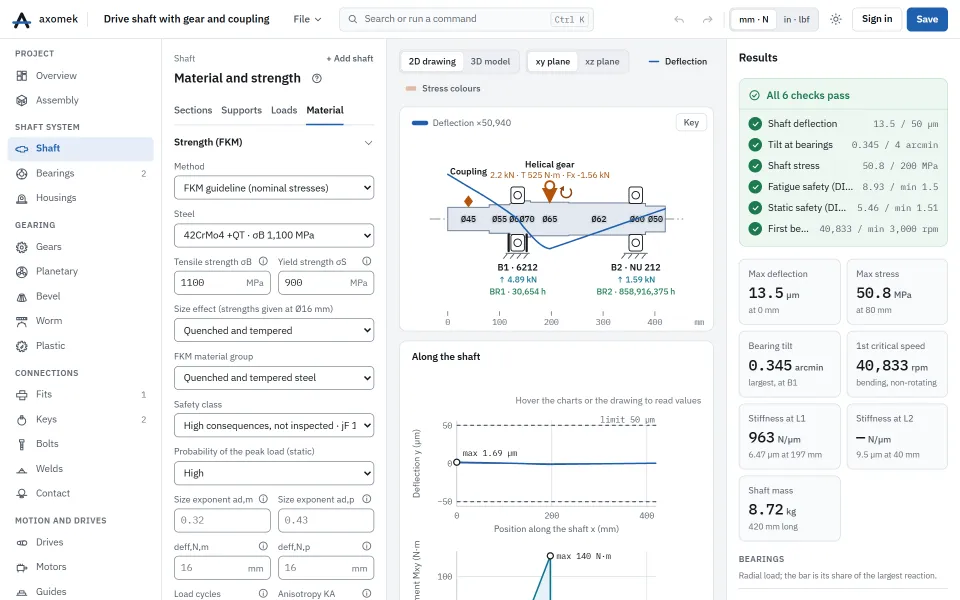
The drive shaft example (42CrMo4 +QT, a helical gear passing 525 N·m to a coupling, six notches) switched to the FKM guideline with the default safety class (high consequences, not inspected) and a finite life of 107 load cycles, shared over its duty cycle of Nominal 60 %, Peak 5 % (loads × 1.6) and Part load 35 % (loads × 0.5 at 1200 rpm).
| Result | Value |
|---|---|
| Fatigue utilisation aBK, over the duty cycle | 0.168 |
| Fatigue safety jD/aBK | 8.93 |
| Safety factor jD | 1.50 |
| KBK in bending at the gear keyway | 1.124 |
| Kf in bending at the gear keyway | 2.901 |
| Static safety jges/aSK, worst load case | 5.46 |
| Safety factor jges | 1.51 |
| Rm at the effective diameter | 911.3 MPa |
A point passes when aBK ≤ 1 and aSK ≤ 1. KBK above 1 is the credit the spectrum gets for its finite life; for a much longer life it falls to 1 and the Peak case alone governs.
The numbers come from the engine: the same commands, run with the axm command line, give them.
The same with the axm command line
axm new ex.axm.json --template drive-shaft
axm apply ex.axm.json {"op":"updateStrength","patch":{"method":"fkm","fkm":{"cycles":10000000}}}
axm solve ex.axm.json --jsonQuestions
Why is there no minimum safety to enter?
The FKM guideline builds its safety factors in: jD and jges follow from the safety class, the probability of the peak load, the casting factor and the temperature. A point passes when its degrees of utilisation aBK and aSK are at most 1.
Miner consistent or Miner elementary?
Miner consistent is the guideline’s preference and the default. Miner elementary (eq. 2.4.42) is the more conservative of the two; both use the effective Miner sum of eq. 2.4.41 unless you give Dm.
How does it differ from DIN 743?
Both assess the same sections with the same nominal stresses. The FKM method states the result as degrees of utilisation with explicit safety factors and handles finite life and load spectra; DIN 743 here is an endurance-limit check that takes the worst load case.