Linear guides
Profile rail guides after ISO 14728: the table load shared over the carriages, equivalent loads with moments, rating life in km and hours, and static safety.
- ISO 14728-1
- ISO 14728-2
The Guides module sizes a profile rail linear guide: one or two rails with one to four carriages each, carrying a table. It shares the table load over the carriages, finds each carriage's equivalent load, and rates the life in kilometres and hours and the static safety. The module sits in the Motion and drives group of the navigation.
Guides stand on their own: they are not linked to a shaft. One project can hold several guides, for example the X and Y axes of a gantry.
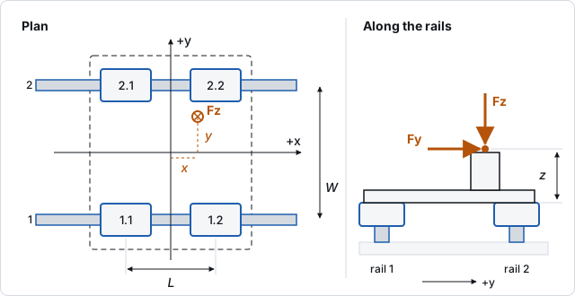
Axes and carriage numbers
- x runs along the rails (the travel), y across them, z up from the carriage mounting surface.
- All load positions are measured from the centre of the carriage pattern.
- Carriages sit at (three or four carriages are spaced evenly between them) and, with two rails, at .
- Carriage 1.1 is rail 1 (at −y), first carriage (at −x). Carriage 2.2 is rail 2 (at +y), last carriage (at +x).
Inputs
Choose + Guide at the top of the list. The inspector shows four groups.
Carriages
| Label | Unit | Notes |
|---|---|---|
| Rolling elements | Balls (p = 3) or Rollers (p = 10/3): the life exponent. | |
| Rating for | 50 km or 100 km (ISO): the distance the dynamic rating refers to. Take it from the catalogue page. | |
| Dynamic rating C | N | Of one carriage. |
| Static rating C₀ | N | Of one carriage. |
| Roll moment M₀x | N·m | Static moment rating of one carriage about x. |
| Pitch moment M₀y | N·m | About y. |
| Yaw moment M₀z | N·m | About z. |
Arrangement
- Rails: One or Two.
- Carriages per rail: 1 to 4.
- Rail spacing W (mm): between the rail centres.
- Carriage spacing L (mm): between the outer carriages of a rail.
Load and motion
| Label | Unit | Notes |
|---|---|---|
| Vertical Fz (down +) | N | Positive presses the table onto the rails; negative lifts it off. |
| Lateral Fy | N | Across the rails. |
| Drive force Fx | N | Along the rails. The drive (screw, belt, motor) carries it; here it only adds moments. |
| Load at x, Load at y | mm | Where the load acts, from the pattern centre. |
| Load height z | mm | Height of the load above the carriages. |
| Stroke | mm | For the life in hours. |
| Double strokes | /min | Forward and back counts as one. |
Enter the resultant of the table, the head and the process load. Weights belong in Fz at their centre of gravity.
Factors and requirements
This group is collapsed. Load factor fW (default 1.2) covers shocks and vibration. Hardness factor fH, Temperature factor fT and Contact factor fC (all 1 by default) reduce the life for soft raceways, high temperatures and carriages mounted close together. Take them from the carriage maker. Min life (default 20 000 h) and Min static safety (default 2) set the checks.
How the load is shared
The table is taken as rigid on equally stiff carriages. A load off the centre tips the table about the pattern:
- roll , positive pressing the +y carriages;
- pitch , positive pressing the +x carriages;
- yaw .
Each carriage takes Fz/n plus its share of roll and pitch in proportion to its distance from the centre. A horizontal force above the carriages presses the carriages on the side it points to.
Moments the pattern cannot react go into the carriages themselves: roll on a single rail, pitch and yaw with one carriage per rail. The equivalent load then counts them through the moment ratings:
With two rails and two or more carriages per rail the moment ratings are not used.
Results
The results column shows the checks and two key results:
- Life (shortest carriage) in hours, with the system life and the shortest life in km.
- Static safety, the smallest C₀/P of the carriages, with the mean speed.
The Details card lists Moments roll / pitch / yaw and, for each carriage, Fz, Fy, P and the life in hours.
The rating life of a carriage is
and the life in hours divides it by the distance travelled per hour, 2 × stroke × double strokes × 60. The system life combines all carriages with the Weibull slope 10/9, : it is shorter than the shortest carriage, as any carriage failing ends the guide's life. This is the same idea as the bearing system life in ISO 281 rating life.
The template
The Ball screw and linear guides template has two rails 300 mm apart with two ball carriages per rail 200 mm apart (C 30 000 N for 100 km, C₀ 50 000 N), loaded with Fz 4400 N and Fy 600 N at x 60, y 80 and z 120 mm, 800 mm stroke and 6 double strokes per minute:
| Result | Value |
|---|---|
| Roll / pitch / yaw | 424 / 264 / 36 N·m |
| Carriage 2.2 (most loaded) | Fz 2467 N, Fy 240 N, P 2707 N, 136 802 h |
| Carriage 1.1 (least loaded) | Fz −266.7 N (lifting), P 326.7 N |
| Shortest / system life | 136 802 h / 120 270 h |
| Static safety | 18.47 |
| Mean speed | 0.16 m/s |
Both checks pass. The same load on a single rail (W not used) puts half of the 424 N·m roll into each carriage. Each P then exceeds 22 000 N, the life falls to 169.5 h and the static safety to 1.984: both checks fail. Roll on a single rail is expensive.
Fixing a failing check
- Spread the pattern: a wider Rail spacing W or Carriage spacing L reduces the share of roll and pitch.
- Use two rails or more carriages per rail, so that moments are reacted by the pattern instead of the carriages.
- Bring the load closer to the pattern centre and lower its height z.
- Choose a larger carriage size (higher C and C₀) or roller carriages.
- For life only: a shorter stroke or fewer double strokes raise the hours, not the km.
Guide view
The Guide view card above the details has two tabs:
- 2D draws the guide From above and From the side. From above: the rails at their spacing, the carriages at theirs, the table, the load point with Fx and Fy, and the stroke with the table dashed at both its ends. From the side: the table load at its height z with Fz and Fx. Each carriage is coloured by the share of its limits it uses: the larger of the static safety's (S₀,min/S₀) and the life's, as a load ratio. Grey is unloaded, red is at a limit. Below, the Carriage loads table gives each carriage's equivalent load P as a bar in the same colour, with Fz, Fy and the share used.
- 3D shows the rails, the carriages in their colours under a see-through table, and the load arrow at the load point. Point at it (or move the keyboard focus to it) and the table runs once over the stroke and back. Drag to turn the view, scroll to zoom.
The rail and carriage sizes in the drawings follow the dynamic rating C (about 15, 25 and 45 mm rails for 10, 30 and 100 kN). They are for the picture only; the results do not use them.
The 3D tab needs WebGL. Where the browser has none, the view stays on the 2D tab and says why. With reduced motion set in the system, nothing moves.
Standards and scope
- Rating life after ISO 14728-1 and static safety after ISO 14728-2, with the life factors fH, fT, fC and fW as catalogues state them.
- The table is rigid and all carriages equally stiff. Elastic tables, carriage preload, rail mounting errors and statically indeterminate stiffness sharing are not modelled.
- One load case per guide: a duty cycle with several loads or a mean load over the stroke is not computed. Use the largest or a weighted mean load.
- Lubrication, seals, the drive force capacity and the rail's own strength are not assessed.
From the command line
axm new axis.axm.json --template linear-axis
axm linear-guide update axis.axm.json LG1 --patch '{"railSpacing":400}'
axm solve axis.axm.json
axm guide guides-screws lists every field.